


Understanding circuit diagrams is a crucial skill for anyone interested in electronics.
These diagrams are visual maps of electrical circuits, using symbols to represent components. For beginners, they can seem complex and intimidating. But with practice, they become easier to read and understand.
Circuit diagrams are essential for building and troubleshooting electronic devices. They provide a clear picture of how components connect and interact. Learning to read them opens up a world of possibilities in electronics.
Each component in a circuit diagram has a unique symbol. Recognizing these symbols is the first step in understanding circuit diagrams. Lines in the diagrams represent wires or connections between components.
Beginners should start with simple circuits. This builds confidence and understanding. As you progress, more complex diagrams will become manageable. Online resources and tutorials can be valuable aids in this learning journey.
Safety is important when working with electronics. Always take precautions to avoid accidents. Understanding circuit diagrams can lead to designing custom projects. This skill is a universal language in electronics, used by engineers and hobbyists alike.
What Are Circuit Diagrams?
Circuit diagrams are technical drawings that represent electrical circuits. They use standardized symbols to illustrate electrical components and connections. These diagrams are vital for designing, building, and troubleshooting electronic systems.
A circuit diagram provides a simplified overview of a circuit's components. It omits physical details, focusing instead on function and relationships. This abstraction makes it easier to understand the circuit's logic.
Key features of circuit diagrams include:
- Symbols: Standardized icons representing components like resistors and capacitors.
- Lines: Indicate connections between components, often corresponding to wires.
- Labels: Details like voltage or resistance values for clarity.
Beginners often find circuit diagrams challenging at first. However, recognizing common symbols and their meanings is the starting point. Over time, this skill turns diagrams from puzzling illustrations into comprehensible guides.
Circuit diagrams range from basic to highly complex. Simple diagrams might show a single LED circuit, while complex ones can represent entire computer systems. Understanding these diagrams is fundamental for anyone engaged in electronics.
Why Learn to Read Circuit Diagrams?
Reading circuit diagrams is a fundamental skill for anyone interested in electronics. They serve as the blueprint for all electronic devices and projects. Without this understanding, building or troubleshooting circuits is challenging.
Circuit diagrams enable you to identify components and their relationships. This ability is crucial for modifying or designing circuits. It also aids in diagnosing issues when devices fail, saving time and resources.
There are several reasons to learn circuit diagrams:
- Communication: Share ideas clearly with engineers and hobbyists.
- Innovation: Design and innovate with custom electronic solutions.
- Efficiency: Troubleshoot and repair devices with ease.
Beyond practical applications, learning to read these diagrams fosters critical thinking. It improves problem-solving skills and enhances creativity.
This knowledge opens doors to advanced studies and careers in electronics and engineering. It is a stepping stone for anyone pursuing electronics as a hobby or profession.
Circuit Diagram Basics: Symbols and Components
Circuit diagrams use symbols to represent electrical components. Each symbol is a simplified drawing of the physical component. Understanding these symbols is crucial for interpreting diagrams.
Symbols are consistent across diagrams, making them a universal language in electronics. Recognizing these symbols helps you decipher circuit layouts and functions. Start by familiarizing yourself with basic symbols like resistors, capacitors, and diodes.
Here's a quick look at some common symbols:
- Resistor: Zigzag line or rectangle.
- Capacitor: Two parallel lines or a straight and a curved line.
- Diode: Triangle pointing to a line.
Wires in circuit diagrams are shown as straight lines. They connect symbols and guide current flow. Always follow these lines to see how components interact in the circuit.
Some diagrams use extra labels and values, like resistance in ohms. These details enhance understanding and accuracy when working with real circuits. Look for these labels to grasp component specifications.
Beginners should focus on mastering these basics. With practice, recognizing symbols will become second nature. This skill is key to designing and troubleshooting circuits effectively.
Circuit symbols are just the beginning, though. Understanding how these components work within a circuit is the next step to mastery. Such knowledge is instrumental in electronics for both hobbyists and professionals.
Common Circuit Symbols Explained
Learning circuit symbols requires patience and practice. Let's explore some common symbols used in circuit diagrams:
Resistors are among the most common elements. Represented by a zigzag or rectangle, they limit current flow.
Capacitors store electrical energy temporarily. They appear as two parallel lines or a line with a curve.
Diodes allow current to flow in one direction only. Their symbol is a triangle pointing to a line, like an arrowhead.
Transistors amplify or switch currents. They have three terminals, often shown with lines and arrows.
Power sources like batteries are essential for circuit operation. They are depicted as a pair of lines, with one longer to indicate polarity.
A ground symbol represents the common return path for current. It is usually three parallel lines tapering to a point.
Switches control the flow of electricity. They are shown as a break in a line that connects with a contact point.
Recognizing these symbols streamlines the process of reading and creating circuit diagrams. It ensures components are correctly identified and assembled for proper operation.
How to Identify Components in a Circuit Diagram
Identifying components within a circuit diagram is straightforward once familiar with basic symbols. Begin by locating the power source, typically at one corner of the diagram.
Next, trace the lines connecting different symbols. Notice how each component links to another. This map reveals how current flows through the circuit.
Focus on the following components:
- Transistors: Key for amplifying signals.
- Switches: Manage connectivity within the circuit.
Recognize components by their symbols and accompanying labels. Values like ohms and voltage may be provided next to components. These details are critical for understanding a component's purpose and functionality.
Practice is essential to gain confidence in component identification. Analyzing sample diagrams builds experience and reinforces your skills.
Finally, use circuit simulation software to test understanding without physical assembly. This software provides a safe environment to visualize and explore circuit behavior.
Understanding Connections and Layouts
Interpreting how components connect in a circuit is crucial. Circuit diagrams use lines to indicate these connections, akin to wires in real life. Comprehending these connections helps visualize circuit functionality.
The layout of a circuit diagram represents the physical placement of components. However, it simplifies the wiring complexity. Clear layouts ensure that the path of the current is easy to follow. This is vital for both assembly and troubleshooting.
Here are key aspects to consider:
- Connection Points: Where wires meet.
- Node Junctions: Indicate multiple connections.
- Labels and Colors: Enhance understanding but vary by diagram.
Understanding layouts involves recognizing different diagram orientations. Some diagrams are more linear, while others are radial. Each style caters to specific circuits and applications.
Practice deciphering various layouts to improve your circuit comprehension. This skill aids in both reading and creating your own diagrams, ensuring accuracy and efficiency in electronic projects.
Series vs. Parallel Circuits
Series and parallel circuits differ mainly in how components connect. This affects current flow and circuit behavior. Understanding these differences is pivotal.
Series Circuits have components linked one after another. Current flows through each component sequentially. A break anywhere disrupts the entire circuit.
Parallel Circuits have components connected across each other. Current can flow through multiple paths. A break in one path doesn't affect others.
Here's a summary of key characteristics:
- Series: Same current throughout, voltage divides.
- Parallel: Same voltage across components, current divides.
- Impact on Performance: Affects brightness in lamps and speed in motors.
Practicing with both series and parallel circuits helps grasp their unique attributes. This understanding is vital for designing effective and reliable circuits. Experiment with basic examples to reinforce these concepts in real-world applications.
Step-by-Step: How to Read a Circuit Diagram
Reading a circuit diagram is like deciphering a map. As mentioned before, start by identifying the power source. This is typically shown with a pair of lines of differing lengths.
Next, locate the connections. Wires or lines represent these connections, guiding the flow from one component to another. Follow these carefully to understand the path the current will take.
Focus on the components. Each component is symbolized uniquely. Familiar symbols include resistors as zigzag lines and capacitors as parallel lines. It’s important to recognize these to understand their role in the circuit.
Examine the layout to discern how components interrelate. Some diagrams are complex; breaking them into segments aids understanding.
Check if components are arranged in series or parallel. This affects both operation and troubleshooting of the circuit.
Here's a simple guide to follow:
- Identify the Power Source: Locate the battery or power line.
- Trace Connections: Follow the wires to understand current paths.
- Recognize Symbols: Understand each component’s purpose.
- Evaluate Layout: Consider series vs. parallel arrangements.
Finally, note any additional labels or values. These provide critical details like resistance, crucial for analysis. By breaking down each segment, reading circuit diagrams becomes less daunting.
Mastering these steps ensures you can approach any circuit diagram with confidence. Practice with different diagrams to enhance your skills and deepen your understanding.
Tips for Beginners: Practice and Resources
Getting started with circuit diagrams might feel daunting, but practice is key. Simple exercises can greatly boost your confidence.
Utilize online simulations. These tools allow you to test and modify virtual circuits, enhancing your understanding without physical components.
Seek out beginner-friendly resources. There are numerous websites, forums, and tutorials dedicated to electronics for beginners. These can offer detailed explanations and community support.
Consider the following resources:
- Online Tutorials: Step-by-step guides that break down complex concepts.
- Simulation Software: Tools like Tinkercad for practicing without hardware.
- Community Forums: Places to ask questions and share experiences.
Experimenting with different circuits is also invaluable. Build simple projects to reinforce your learning. Hands-on experience will help solidify your understanding of circuit diagram basics, guiding you towards more complex creations.
Common Mistakes and How to Avoid Them
When learning circuit diagrams, beginners often face common pitfalls. Recognizing these early can save time and frustration.
A frequent mistake is misreading symbols. Ensure you familiarize yourself with every symbol's correct representation and meaning.
Another issue is poor connections in diagrams. Many overlook the importance of clear, complete paths. Pay attention to the way wires connect components.
Here's how to minimize errors:
- Double-Check Symbols: Verify every component's symbol before proceeding.
- Trace Connections: Follow each wire and ensure it logically connects components.
- Use Reference Guides: Consult reliable sources to clarify uncertainties.
Practicing these strategies will help you create clearer, more accurate circuit diagrams and ultimately enhance your skills in electronics for beginners.
Simple Circuit Examples for Beginners
Exploring simple circuit examples can solidify your understanding. Let's look at a basic LED circuit, an ideal starting point for beginners.
This circuit includes a resistor, an LED, and a battery. The resistor limits the current to prevent the LED from burning out.
Another example is a simple buzzer circuit. It comprises a power source, a switch, and a buzzer. This circuit demonstrates how switches can control devices.
List of simple circuits to try:
- LED Circuit
- Buzzer Circuit
- Simple Motor Circuit
These circuits are not complex, making them excellent for practice. Each builds on the basic components and connections discussed earlier.
Engaging with these straightforward circuits helps reinforce essential skills. By practicing with them, you gradually develop the confidence needed to tackle more complex designs.
Next Steps: Building and Testing Circuits
Now that you understand circuit diagrams, take the next step by building circuits. Start with simple projects to apply your new knowledge effectively.
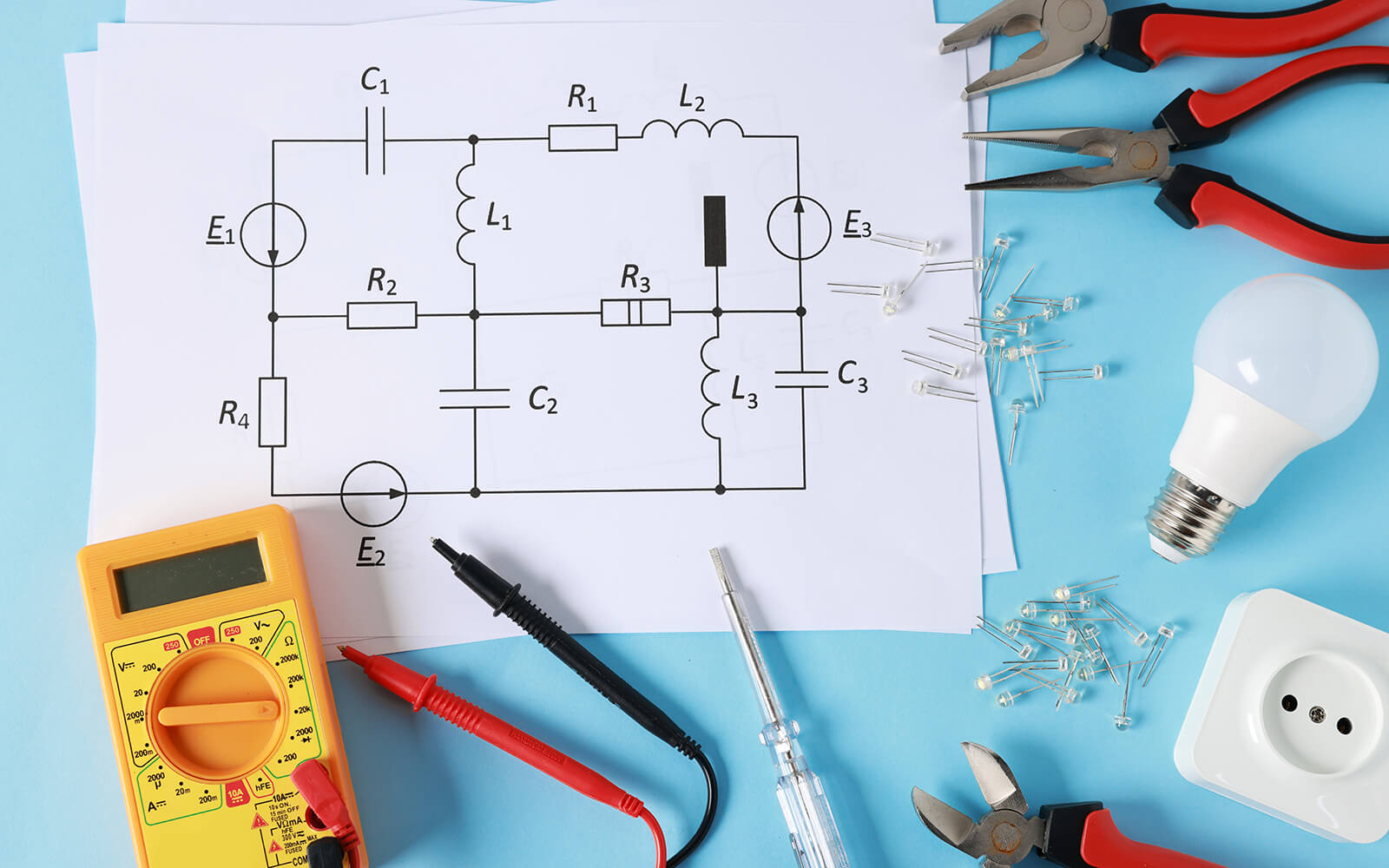
Testing your circuits is crucial. It ensures everything works correctly. Use a multimeter to measure voltage and current. This tool helps confirm connections and verify circuit performance.
Here are some steps for your building and testing journey:
- Choose a simple circuit diagram
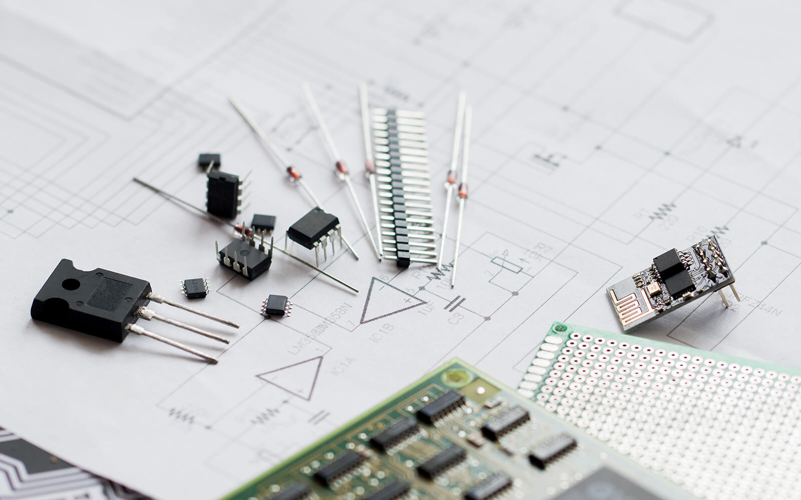
- Gather all necessary components
- Assemble the circuit on a breadboard
- Use a multimeter to test the circuit
Patience is key. Practicing these steps consistently will solidify your skills and prepare you for more advanced electronic adventures.
Your Path Forward in Electronics
Embarking on a journey in electronics begins with understanding circuit diagrams. These foundational skills open doors to endless possibilities and creative projects. As you grow more comfortable with circuits, you will start to see the underlying logic in devices around you.
Keep exploring and practicing your new skills. Continuous learning is your best ally in mastering electronics. With persistence, you will soon be designing and building your own innovative projects. The world of electronics is vast and full of exciting opportunities.
Breadboards in Action: Your Hands-On Bridge Between Diagrams and Real Circuits
When you're learning to navigate circuit diagrams, turning those symbols into actual components can feel like magic. Breadboards bring that magic to life - no soldering needed.
Just like reading a schematic gives you a blueprint, a breadboard lets you translate that blueprint into a physical circuit - quickly and flexibly. With no soldering involved, you can explore connections, move components around, and iterate until it all clicks.


Explore our Proto Accessories – a curated selection of breadboards, jumper wires, power modules, and other essentials for rapid prototyping. Whether you're testing components or building full circuit setups, these tools are perfect for fast, flexible development.
Build, test, iterate – all without picking up a soldering iron.
ABOUT MIKROE
MIKROE is committed to changing the embedded electronics industry through the use of time-saving industry-standard hardware and software solutions. With unique concepts like Remote Access, One New Product/Day, Multi-Architectural IDE and most recently, the EmbeddedWiki™ platform with more than million ready-for-use projects, MIKROE combines its dev boards, compilers, smart displays, programmers/debuggers and 1850+ Click peripheral boards to dramatically cut development time. mikroBUS™; mikroSDK™; SiBRAIN™ and DISCON™ are open standards and mikroBUS only has been adopted by over 100 leading microcontroller companies and integrated on their development boards.
Your MIKROE


