


Breadboards are a staple in the world of electronics. They are essential tools for prototyping and testing circuits.
But what exactly is a breadboard?
It's a device that allows you to create temporary circuits. This is done without the need for soldering, making it perfect for experimenting and learning.
This guide will delve into the intricacies of using a breadboard. It will cover everything from understanding the layout to building your own circuits.
Whether you're a hobbyist, a student, or a DIY enthusiast, this guide is for you. Let's demystify the breadboard and make electronics more accessible.
Introduction to Breadboards
Breadboards are versatile tools used for creating and testing circuits. They are perfect for beginners and experts alike. The main advantage is their reusability, allowing countless configurations without soldering.
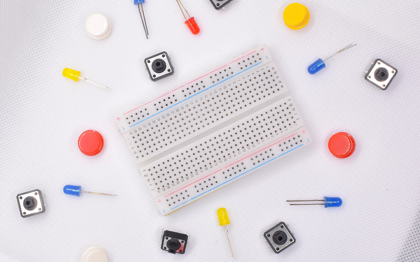
The structure of a breadboard is simple yet effective. It consists of a grid of holes where components can be easily inserted. The rows and columns are interconnected, facilitating various circuit designs. Understanding this layout is crucial for effective circuit assembly.
Common applications include educational settings, where learners explore electronic concepts. They are also vital for prototyping new ideas before committing to more permanent solutions. Their flexibility makes them indispensable in the electronics domain.
Below are some key features that make breadboards unique:
- Reusable with no soldering required.
- Supports rapid prototyping.
- Ideal for educational and experimental purposes.
- Available in various sizes to suit project needs.
Grasping the basics of breadboarding paves the way for more complex projects and innovations. In essence, a breadboard is the first step into a fascinating world of electronics.
What is a Breadboard?
A breadboard is a tool used to construct temporary electronic circuits. It comprises a rectangular plastic board with a grid of holes. These holes allow electronic components and wires to be easily inserted. Inside the board, metal strips connect these holes to create rows or columns, facilitating component connections.
This design enables the rapid assembly and disassembly of circuits. Users can modify a circuit without the complexity of soldering. This makes breadboards especially useful for beginners and those testing circuit functionality. Breadboards come in various sizes and types, tailored for different project needs. Their modularity and simplicity are key features that empower users to explore electronics without constraints.
Why is it Called a Breadboard?
The term "breadboard" has an interesting origin that dates back to the early days of electronics. Historically, inventors used actual breadboards, the wooden boards for slicing bread, to mount electrical components. These wooden boards provided a convenient surface for arranging circuits.
As electronics evolved, the name stuck, eventually describing the plastic boards we know today. Early experimenters would hammer nails into the wood and use the nails as connection points. Modern breadboards replicate this concept with holes and metal strips instead of wood and nails.
The evolution from wood to plastic was driven by the need for reusability and ease of use. Today's breadboards allow quick circuit modifications, reflecting their history of practicality. Understanding their name provides a glimpse into the ingenuity and resourcefulness of early innovators.
Different Types of Breadboards
Breadboards come in various types to accommodate different needs. The most common are full-size, half-size, and mini breadboards. Full-size breadboards offer ample space for larger, more complex circuits. They are ideal for projects where component count and layout flexibility are crucial.
Half-size breadboards offer a balance between space and compactness. They provide sufficient room for moderately complex circuits while being easy to store. Mini breadboards are for small, simple projects or when space is limited. They are portable and ideal for quick tests or educational purposes.
Choosing the right type depends on the project's scale and components involved. Each type offers unique advantages, whether you prioritize size, portability, or complexity. Understanding the options available ensures you select the best breadboard for your specific needs.
Understanding Breadboard Layout
Grasping the layout of a breadboard is crucial for successful circuit assembly. The board is divided into rows and columns of holes. Each hole allows the insertion of components and wires.
Typically, the breadboard is separated into sections for power distribution and component connections. The outer sections, known as power rails, distribute voltage throughout the board. These rails are usually marked with red and blue lines to signify positive and negative connections.
The inner areas of the breadboard are for connecting components. The holes here are often grouped in rows, offering flexibility in designing circuits. Mastering how these sections interact is key to building functional circuits. This knowledge helps in avoiding shorts and making circuits efficient.
Here are some essentials to remember about the breadboard layout:
- Power rails for distributing voltage.
- Inner rows for component connections.
- Grouped rows that allow for flexible circuit designs.
Understanding this layout allows for efficient use of space and ensures connections are secure. The simplicity of the breadboard design belies its powerful role in circuit prototyping.
Breadboard Components
Various components can be used with a breadboard to create circuits. Common ones include resistors, capacitors, transistors, and LEDs. These components are easily inserted into the holes on the board. They help in constructing a circuit by performing essential functions such as resistance, capacitance, and light emission.
Another crucial element is the jumper wire. These wires connect different parts of the breadboard to build circuits. They can bridge gaps between components or extend connections from power rails. The correct use of components and wires is foundational to successful breadboarding.
Diagram of Breadboard
Understanding a diagram of a breadboard assists in visualizing circuit connections. Such diagrams illustrate the layout of components and wires on the board. They serve as blueprints for assembly.
Typically, a breadboard diagram includes visual indicators of power rails, component placements, and wire connections. These elements help in planning and executing the circuit effectively.
Diagrams are invaluable for troubleshooting. They provide a clear reference when comparing the actual circuit to the intended design. This visual tool is essential for both beginners and seasoned electronics enthusiasts. The presence of a diagram accelerates the prototyping process and aids in error detection.
Breadboard Wiring Diagram
A breadboard wiring diagram depicts the intricate connections within a circuit. These diagrams use lines and symbols to indicate where components and wires meet. They provide a visual roadmap for constructing circuits accurately.
These diagrams help ensure that all connections are correctly established. They minimize the likelihood of errors by providing a clear layout for wire placement. Utilizing a wiring diagram can simplify the assembly process significantly.
Such diagrams also facilitate collaboration. They allow multiple individuals to understand the circuit layout and contribute to the project smoothly. Having a solid wiring diagram is crucial for building complex circuits and ensuring that they function as intended.
How Does a Breadboard Work?
Breadboards are ingenious tools designed for prototyping and testing electronic circuits without soldering. Their magic lies in their grid of interconnected holes. Components and wires can be inserted and rearranged easily, allowing for quick adjustments and troubleshooting.
Understanding the function of a breadboard requires a look at its internal connections. Beneath the surface, metal strips run the length of the board. These strips create conductive paths between the holes. When you insert a component into a hole, it becomes electrically connected through these strips.
The modular nature of breadboards makes them reusable. You can experiment with various layouts until you find the optimal configuration. This adaptability is crucial for projects requiring frequent modifications.
Breadboards are divided into separate sections: the central terminal strips and the outer power rails. Terminal strips are for placing components. Power rails distribute the necessary voltage. The flexibility of breadboards empowers electronics enthusiasts. They can test designs without permanent changes, fostering innovation and learning.
Electrical Connections on a Breadboard
Electrical connections on a breadboard occur through internal metal strips. These strips connect holes in rows, creating conductive pathways. This allows current to flow between connected components.
Each row acts like a mini-circuit in itself. Components in the same row are electronically connected. Power rails, usually in parallel rows along the board, distribute voltage. They maintain consistent power supply to various sections.
Jumper wires link components across different rows and areas. Strategically using jumper wires ensures efficient circuit functioning. The design enables complex circuits without the need for soldered joints.
Breadboard Circuit Basics
Breadboard circuits rely on the basic principle of electrical connectivity. Components are placed into the board's holes to create a complete circuit. This setup mimics permanent circuits but offers flexibility.
Each piece has a role in the function. Resistors control current flow; capacitors store energy; diodes regulate direction. Understanding the function of each component helps in forming effective circuits.
Powering the breadboard is essential. A power supply connects to the rails, energizing the components. The goal is a closed loop: current travels through power, components, and back. Monitoring this loop ensures the circuit operates correctly.
How to Use a Breadboard
Using a breadboard effectively is a blend of art and science. Start by planning your circuit with a schematic. Identify where each component and connection will go. This saves time and reduces errors.
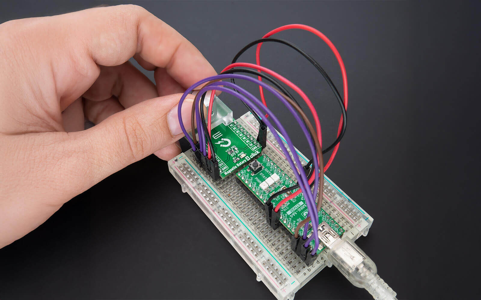
Insert components into the holes. Ensure that you follow the planned layout. Use jumper wires to connect different sections. This creates pathways for electricity to flow.
Always connect power lines last to prevent short circuits. Double-check all connections before applying power. Test the circuit with a multimeter to ensure it’s working. Breadboards offer a hands-on approach to learning and innovating in electronics.
Building Circuits on a Breadboard
Building circuits on a breadboard is an engaging way to explore electronics. Breadboards provide a platform to test ideas before committing to permanent setups. They allow you to tweak designs effortlessly and learn from real-world experiments.
Start with a clear schematic. This blueprint is crucial for understanding the components and connections. Having a well-drawn plan reduces mistakes and streamlines the building process.
Breadboards are versatile. They support a range of components such as resistors, capacitors, and LEDs. The layout is modular, accommodating additional elements as needed. This flexibility is ideal for prototyping small and large scale projects.
Always use good quality components. Poor quality materials can lead to faulty connections and inaccurate results. Ensure all components are the correct specifications for your design.
Safety is paramount. Avoid short circuits by meticulously checking connections. Make sure your power supply matches the voltage requirements of your components.
A breadboard's reusability is one of its strengths. As you build, don't hesitate to make changes. This dynamic aspect helps foster better understanding and creativity in electronic design.
Step-by-Step: How to Create a Circuit on a Breadboard
Creating a circuit on a breadboard can be straightforward. First, gather all necessary components and tools. This includes a schematic diagram, jumper wires, and a power supply.
Begin by identifying the power rails on your breadboard. Connect the positive and negative terminals of your power source accordingly. This ensures a steady power flow.
Insert your components according to the schematic. Place resistors, capacitors, and other elements in the designated rows. Be meticulous about placement to match the layout plan.
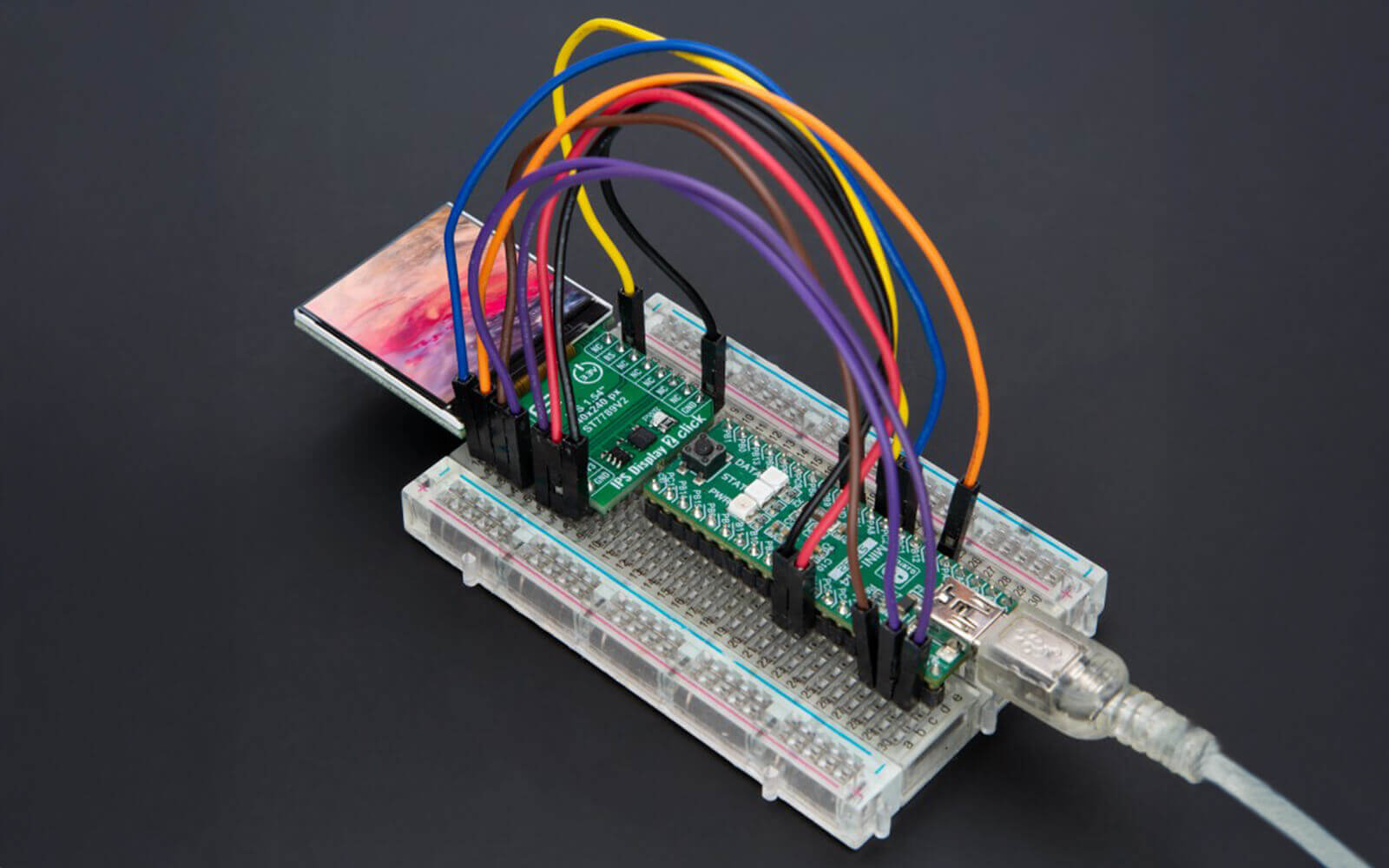
Use jumper wires to connect components across the board. Verify that wires align with corresponding nodes in your diagram. This completes electrical pathways.
Double-check all connections for accuracy before powering the circuit. Power up your breadboard, then test it with a multimeter. Ensure that current flows correctly.
Breadboard Circuit Examples
Breadboards cater to a myriad of circuit designs. Here are some examples for varying skill levels:
- LED Blink: A simple circuit with an LED that turns on and off using a resistor and a power source.
- Sound Activated LED: Utilize a microphone, resistor, and LED to light up when sound is detected.
- Temperature Sensor Circuit: Incorporate a thermistor to measure temperature, displayed via a connected LED.
These examples encourage hands-on learning. As you gain confidence, try more complex configurations.
The LED blink circuit is often a beginner's favorite. Its simplicity shows basic electronic concepts in action. The sound-activated circuit introduces sound sensing via basic components.
For the temperature sensor, interfacing with a thermometer adds an extra layer of interest. Such circuits exemplify real-world applications and encourage further exploration.
Simple Breadboard Circuits for Beginners
Simple circuits are excellent starting points. They require fewer components and offer quick results. These projects help build foundational skills.
Here’s a list of beginner-friendly circuits:
- Basic LED Circuit: Connect an LED with a current-limiting resistor to a power source.
- Buzzer Circuit: Create an alert system with a small buzzer and a switch.
- Light Sensor: Use a photoresistor to modulate LED brightness based on ambient light.
The basic LED circuit demonstrates component connections. It's ideal for those learning to use jumpers and power rails.
In the buzzer circuit, you'll learn about switches and creating interactive designs. The light sensor circuit introduces sensors and varying resistance.
Each circuit expands understanding of the fundamental principles of electronics. These projects build confidence for more advanced creations.
Troubleshooting Breadboard Circuits
Troubleshooting circuits on a breadboard is crucial to successful electronics projects. Even experienced hobbyists encounter issues that need problem-solving skills. Identifying errors early prevents major setbacks later in the project.
Start by systematically checking each connection. Often, problems arise from simple mistakes like misconnected wires or misplaced components. Each connection must be correctly aligned with the intended nodes, so a thorough review is necessary.
A common culprit in faulty circuits is power supply issues. Ensure the power rails are properly connected and that the power supply delivers the correct voltage. Using a multimeter to verify voltage and continuity can catch many potential issues.
Be mindful of component quality and orientation. Components must not only be properly spec'd but also correctly oriented. Misalignment, especially in polarized components like diodes and capacitors, can lead to malfunctioning circuits.
If problems persist, consider environmental factors. Ensure the breadboard is free from dust or debris, which may cause unwanted conductivity. A clean work environment helps maintain the integrity of connections.
It's beneficial to develop a habit of documenting your setup before making any changes. This makes it easier to backtrack when issues arise. Clear notes and sketches can save time and effort in troubleshooting.
Common Issues and Solutions
Some frequent issues in breadboard projects include poor connections and incorrect wiring. Loose jumper wires or improperly inserted components are common mistakes.
Short circuits can cause components to overheat or fail. Double-check connections for accidental contact. Ensure all power supplies align with circuit requirements.
Another common issue is incorrect component orientation. Check that diodes, LEDs, and other polarized parts face the correct direction. Consistency in these details helps prevent errors.
Use a multimeter to verify component functionality and power delivery. If a circuit does not operate, check every part individually. This approach often reveals hidden issues.
Breadboard Connection Diagram for Troubleshooting
A breadboard connection diagram is a valuable troubleshooting tool. It serves as a reference map, illustrating how each component should connect. Having an accurate diagram helps identify where connections may have gone wrong.
When creating a connection diagram, focus on clarity and completeness. Label all components, jumper wires, and power connections. This ensures every aspect of the circuit is easily traceable.
Use the diagram to compare with your physical setup. Look for discrepancies between the intended and actual connections. This comparison often highlights the root of the problem quickly.
Revisiting the diagram ensures each component is placed correctly. Verify resistors are within tolerance, and jumpers align perfectly. Attention to detail helps resolve issues without guesswork.
Tips for Success in Breadboard Electronics
Achieving success in breadboard electronics involves patience and preparation. Begin each project with a clear plan and precise diagrams. These foundational steps guide your work and help minimize errors.
Adopt a methodical approach. Check connections consistently and test each section before proceeding. Incremental testing prevents small errors from compounding into larger issues.
Keep your workspace organized and clean. An orderly environment minimizes mistakes and makes components easy to locate. Use color-coded jumpers to simplify tracking different connections.
Continually improve your breadboard technique by learning from each project. Reflect on challenges faced and how they were resolved. This iterative process develops both skill and understanding.
Document each step and any changes. Clear notes facilitate troubleshooting and provide insight into your process. They become a reference for future projects or troubleshooting similar issues.
Always stay curious and open to learning new techniques. Engage with electronics communities or online forums for fresh ideas and advice. Collaboration and shared knowledge enhance expertise in breadboard electronics.
Breadboards in Action: Products & Tools
Want to bring your circuit ideas to life without soldering? Breadboards make it easy – and we’ve got the tools to help.
 Breadboard Mini Self-Adhesive
  Breadboard Clear Self-Adhesive 830 points
  Breadboard Clear Self-Adhesive 400 points
Explore our Proto Accessories – a curated selection of breadboards, jumper wires, power modules, and other essentials for rapid prototyping. Whether you're testing components or building full circuit setups, these tools are perfect for fast, flexible development.
Build, test, iterate – all without picking up a soldering iron.
ABOUT MIKROE
MIKROE is committed to changing the embedded electronics industry through the use of time-saving industry-standard hardware and software solutions. With unique concepts like Remote Access, One New Product/Day, Multi-Architectural IDE and most recently, the EmbeddedWiki™ platform with more than million ready-for-use projects, MIKROE combines its dev boards, compilers, smart displays, programmers/debuggers and 1800+ Click peripheral boards to dramatically cut development time. mikroBUS™; mikroSDK™; SiBRAIN™ and DISCON™ are open standards and mikroBUS only has been adopted by over 100 leading microcontroller companies and integrated on their development boards.
Your MIKROE


