


OFF
GO LOCAL
| Company | Stock | Price |
|---|---|---|


MIKROE-5271
20 g
Status:
Balancer 4 Click is a compact add-on board optimized for overvoltage protection balancing the voltage of serially connected batteries. This board features the MP2672A, a highly integrated, flexible switch-mode battery charger for Lithium-Ion batteries with two cells in series from Monolithic Power Systems (MPS). The MP2672A has a narrow voltage DC (NVDC) power structure and monitors the voltage across each cell, equalizing the cell’s voltages if the difference between the two cells exceeds the mismatch threshold. It also has two selective operating modes with configurable output current up to 2A via register setting via I2C serial interface, alongside selectable MP2672A power supply, LED indication, and protection features allowing a reliable operation. This Click board™ is applicable for a wide range of portable applications, Point-of-Sale (POS) machines, general two-cell applications, and more.
Balancer 4 Click is supported by a mikroSDK compliant library, which includes functions that simplify software development. This Click board™ comes as a fully tested product, ready to be used on a system equipped with the mikroBUS™ socket.
This product is no longer in stock
Availability date:
OFF
| Company | Stock | Price |
|---|---|---|
Balancer 4 Click as its foundation uses the MP2672A, a highly integrated and flexible switch-mode battery charger for two-cell Lithium-Ion batteries in series from Monolithic Power Systems (MPS). The MP2672A features a cell balance function that monitors the voltage across each cell and equalizes them if the difference exceeds the mismatch threshold. It features up to 2A of programmable charge current for batteries with two cells in series, alongside protections like battery temperature monitoring, programmable charging safety timer protection, JEITA-compliant battery NTC monitoring, cell over-voltage protection (OVP), thermal regulation, and thermal shutdown.
The MP2672A has a narrow voltage DC (NVDC) power structure. It automatically detects the battery voltage and charges it in three phases: pre-charge, constant current, and voltage charge. With a deeply discharged battery, the MP2672A regulates the system output to a minimum voltage level, which powers the system instantly while simultaneously charging the battery via integrated FET. It also offers flexible new charging cycle initiation compatible with Standalone mode and Host-control mode of operation selectable through an onboard switch labeled as HOST SEL.
Diverse and robust protections include a thermal regulation loop to decrease the charge current in case the junction temperature exceeds the thermal loop threshold and battery temperature protection compliant with JEITA standards. Other safety features include input over-voltage protection (OVP), battery OVP, thermal shutdown, battery temperature monitoring, and a configurable backup timer to prevent prolonged charging of a dead battery.
Balancer 4 Click communicates with MCU using the standard I2C 2-Wire interface to read data and configure settings, supporting a Standard Mode operation up to 100kHz. It also has two LED indicators, red and green, marked with CHARGE and POWER, which can visually show the existence of a valid power supply to the MP2672A and the active status of the battery charging process. Also, an NTC function is available for temperature-qualified charging, where the MP2672A continuously monitors the battery’s temperature by measuring the voltage on the onboard NTC header pins.
This Click board™ can operate with both 3.3V and 5V logic voltage levels selected via the VCC SEL jumper. It allows both 3.3V and 5V capable MCUs to use the communication lines properly. Additionally, there is a possibility for the MP2672A power supply selection via jumper labeled as VIN SEL to supply the MP2672A from an external power supply terminal in the range from 4V to 5.75V or with 5V voltage level from mikroBUS™ power rail. However, the Click board™ comes equipped with a library containing easy-to-use functions and an example code that can be used, as a reference, for further development.
Type
Battery charger
Applications
Can be used for portable applications, Point-of-Sale (POS) machines, general two-cell applications, and more
On-board modules
MP2672A - highly integrated and flexible switch-mode battery charger from Monolithic Power Systems (MPS)
Key Features
Two-cell Lithium-Ion batteries in series, up to 2A configurable charge current, compatible with Host-control or Standalone mode, NVDC power path management, integrated cell-balancing circuit for
mismatched cells, status indicators, I2C interface, NTC, and more
Interface
I2C
Feature
No ClickID
Compatibility
mikroBUS™
Click board size
L (57.15 x 25.4 mm)
Input Voltage
3.3V or 5V,External
This table shows how the pinout on Balancer 4 Click corresponds to the pinout on the mikroBUS™ socket (the latter shown in the two middle columns).
| Notes | Pin | Pin | Notes | ||||
|---|---|---|---|---|---|---|---|
| NC | 1 | AN | PWM | 16 | NC | ||
| NC | 2 | RST | INT | 15 | NC | ||
| NC | 3 | CS | RX | 14 | NC | ||
| NC | 4 | SCK | TX | 13 | NC | ||
| NC | 5 | MISO | SCL | 12 | SCL | I2C Clock | |
| NC | 6 | MOSI | SDA | 11 | SDA | I2C Data | |
| Power Supply | 3.3V | 7 | 3.3V | 5V | 10 | 5V | Power Supply |
| Ground | GND | 8 | GND | GND | 9 | GND | Ground |
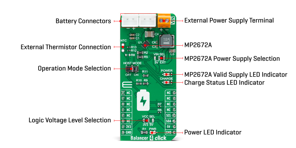
| Label | Name | Default | Description |
|---|---|---|---|
| LD1 | PWR | - | Power LED Indicator |
| LD2 | POWER | - | MP2672A Valid Supply LED Indicator |
| LD3 | CHARGE | - | Charge Status LED Indicator |
| JP1 | VCC SEL | Left | Logic Level Voltage Selection 3V3/5V: Left position 3V3, Right position 5V |
| JP2 | VIN SEL | Right | MP2672A Power Supply Selection 5V/EXT: Left position 5V, Right position EXT |
| J1 | NTC | Unpopulated | External Thermistor Connection Header |
| SW1 | HOST MODE | Right | Operation Mode Selection |
| Description | Min | Typ | Max | Unit |
|---|---|---|---|---|
| Supply Voltage | 3.3 | - | 5 | V |
| External Supply Voltage VIN | 4 | - | 5.75 | V |
| Battery Pack Voltage | - | - | 9 | V |
| Output Current | - | - | 2 | A |
| Operating Temperature Range | -40 | +25 | +120 | °C |
We provide a library for the Balancer 4 Click as well as a demo application (example), developed using MikroElektronika compilers. The demo can run on all the main MikroElektronika development boards.
Package can be downloaded/installed directly from NECTO Studio Package Manager(recommended way), downloaded from our LibStock™ or found on Mikroe github account.
Library Description
This library contains API for Balancer 4 Click driver.
Key functions
balancer4_write_register This function writes a desired data byte to the selected register by using I2C serial interface.
balancer4_write_and_verify_register This function writes a desired data byte to the selected register and verifies if is is written correctly by reading it.
balancer4_read_register This function reads a data byte from the selected register by using I2C serial interface.
Example Description
This example demonstrates the use of Balancer 4 Click board™ by configuring the click board for charging and then reading the status and fault registers.
void application_task ( void )
 {
     uint8_t status, fault;
     if ( BALANCER4_OK == balancer4_read_register ( &balancer4, BALANCER4_REG_STATUS, &status ) )
     {
         log_printf ( &logger, "rn - STATUS - rn", status );
         log_printf ( &logger, " Battery status: " );
         if ( status & BALANCER4_STATUS_BATTERY_MISSING )
         {
             log_printf ( &logger, "missingrn" );
         }
         else
         {
             log_printf ( &logger, "presentrn" );
             log_printf ( &logger, " Charging status: " );
             switch ( status & BALANCER4_STATUS_CHG_STAT_MASK )
             {
                 case BALANCER4_STATUS_NOT_CHARGING:
                 {
                     log_printf ( &logger, "not chargingrn" );
                     break;
                 }
                 case BALANCER4_STATUS_PRE_CHARGE:
                 {
                     log_printf ( &logger, "pre-chargern" );
                     break;
                 }
                 case BALANCER4_STATUS_CONSTANT_CHARGE:
                 {
                     log_printf ( &logger, "constant current or constant voltage chargern" );
                     break;
                 }
                 case BALANCER4_STATUS_CHARGING_COMPLETE:
                 {
                     log_printf ( &logger, "charging completern" );
                     break;
                 }
             }
         }
     }
     if ( BALANCER4_OK == balancer4_read_register ( &balancer4, BALANCER4_REG_FAULT, &fault ) )
     {
         if ( fault )
         {
             log_printf ( &logger, "rn - FAULT - rn" );
             if ( fault & BALANCER4_FAULT_WD )
             {
                 log_printf ( &logger, " The watchdog timer has expiredrn" );
             }
             if ( fault & BALANCER4_FAULT_INPUT )
             {
                 log_printf ( &logger, " Input OVP has occuredrn" );
             }
             if ( fault & BALANCER4_FAULT_THERMAL_SD )
             {
                 log_printf ( &logger, " Thermal shutdownrn" );
             }
             if ( fault & BALANCER4_FAULT_TIMER )
             {
                 log_printf ( &logger, " The safety timer has expiredrn" );
             }
             if ( fault & BALANCER4_FAULT_BAT )
             {
                 log_printf ( &logger, " Battery OVP has occuredrn" );
             }
             switch ( fault & BALANCER4_FAULT_NTC_MASK )
             {
                 case BALANCER4_FAULT_NTC_COLD:
                 {
                     log_printf ( &logger, " An NTC cold fault has occuredrn" );
                     break;
                 }
                 case BALANCER4_FAULT_NTC_COOL:
                 {
                     log_printf ( &logger, " An NTC cool fault has occuredrn" );
                     break;
                 }
                 case BALANCER4_FAULT_NTC_WARM:
                 {
                     log_printf ( &logger, " An NTC warm fault has occuredrn" );
                     break;
                 }
                 case BALANCER4_FAULT_NTC_HOT:
                 {
                     log_printf ( &logger, " An NTC hot fault has occuredrn" );
                     break;
                 }
             }
         }
     }
     Delay_ms ( 500 );
 }
The full application code, and ready to use projects can be installed directly from NECTO Studio Package Manager(recommended way), downloaded from our LibStock™ or found on Mikroe github account.
Other Mikroe Libraries used in the example:
Additional notes and informations
Depending on the development board you are using, you may need USB UART click, USB UART 2 Click or RS232 Click to connect to your PC, for development systems with no UART to USB interface available on the board. UART terminal is available in all MikroElektronika compilers.
This Click board™ is supported with mikroSDK - MikroElektronika Software Development Kit. To ensure proper operation of mikroSDK compliant Click board™ demo applications, mikroSDK should be downloaded from the LibStock and installed for the compiler you are using.
For more information about mikroSDK, visit the official page.
NOTE: Please be advised that any peripheral devices or accessories shown connected to the Click board™ are not included in the package. Check their availability in our shop or in the YMAN section below.

$889.00

$95.00

$549.00

$299.00

$29.00

$29.00

$6.59

$3.60

$119.00

$449.00

$349.00

$349.00

$349.00

$299.00

$269.00

$249.00

$209.00
