


OFF
GO LOCAL
| Company | Stock | Price |
|---|---|---|


MIKROE-5671
16 g
Status:
Accel 29 Click is a compact add-on board that contains an acceleration sensor. This board features the ADXL314, a three-axis ±200g accelerometer from Analog Devices. The ADXL314 offers 16-bit digital output data with a configurable host interface that supports SPI and I2C serial communication. An integrated memory management system with a 32-level FIFO buffer can store data to minimize host processor activity and lower overall system power consumption. Low power modes enable intelligent motion-based power management with threshold sensing and active acceleration measurement at low power dissipation. This Click board™ is suitable for multiple applications such as motion-activated functions, shock detection, high-force event detection, and more.
Accel 29 Click is fully compatible with the mikroBUS™ socket and can be used on any host system supporting the mikroBUS™ standard. It comes with the mikroSDK open-source libraries, offering unparalleled flexibility for evaluation and customization. What sets this Click board™ apart is the groundbreaking ClickID feature, enabling your host system to seamlessly and automatically detect and identify this add-on board.
This product is no longer in stock
Availability date:
OFF
| Company | Stock | Price |
|---|---|---|
Accel 29 Click is based on the ADXL314, a complete three-axis ±200g acceleration measurement system from Analog Devices, operating at low power levels. The ADXL314 measures both dynamic accelerations resulting from motion or shock and static accelerations, such as gravity. It provides digital output data formatted as 16-bit, with acceleration reported digitally through a configurable and selectable serial interface. The ADXL314 automatically modulates its power consumption proportionately to its output data rate. If additional power savings are desired, it also offers lower power modes, enabling intelligent motion-based power management with threshold sensing and active acceleration measurement at low power dissipation.
The ADXL314 is based on a polysilicon surface-micromachined structure built on top of a silicon wafer that suspends the structure over the surface of the wafer, providing resistance against forces due to applied acceleration. Deflection of the structure is measured using differential capacitors that consist of independent fixed plates and plates attached to the moving mass. Acceleration deflects the proof mass and unbalances the differential capacitor, producing a sensor output whose amplitude is proportional to acceleration. Phase-sensitive demodulation is used to determine the magnitude and polarity of the acceleration.
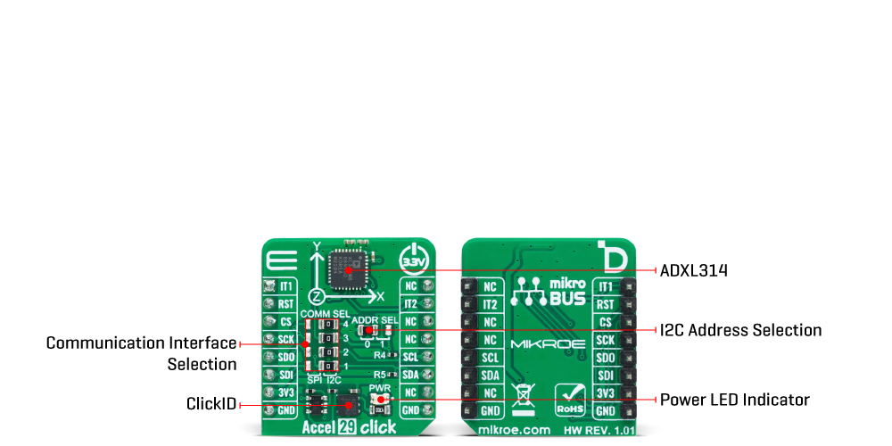
As mentioned, the acceleration data is accessed through I2C or SPI interface with a maximum frequency of 400kHz for I2C and 5MHz for SPI communication. The selection is made by positioning SMD jumpers labeled COMM SEL appropriately. Note that all the jumpers' positions must be on the same side, or the Click board™ may become unresponsive. While the I2C interface is selected, the ADXL314 allows choosing the least significant bit (LSB) of its I2C slave address using the SMD jumper labeled ADDR SEL.
This board also possesses two interrupts, IT1 and IT2, routed to, where by default, the AN and INT pins stand on the mikroBUS™ socket, entirely programmed by the user through a serial interface. They signal MCU that a motion event has been sensed.
This Click board™ can only be operated with a 3.3V logic voltage level. The board must perform appropriate logic voltage level conversion before using MCUs with different logic levels. However, the Click board™ comes equipped with a library containing functions and an example code that can be used as a reference for further development.
Type
Motion
Applications
Can be used for multiple applications such as motion-activated functions, shock detection, high-force event detection, and more
On-board modules
ADXL314 - three-axis accelerometer from Analog Devices
Key Features
±200g measurement range, low power consumption, user-selectable bandwidth, fixed 13-bit output resolution, selectable interface, embedded memory management system with FIFO technology, interrupt, and more
Interface
I2C,SPI
Feature
ClickID
Compatibility
mikroBUS™
Click board size
S (28.6 x 25.4 mm)
Input Voltage
3.3V
This table shows how the pinout on Accel 29 Click corresponds to the pinout on the mikroBUS™ socket (the latter shown in the two middle columns).
| Notes | Pin | Pin | Notes | ||||
|---|---|---|---|---|---|---|---|
| Interrupt 1 | IT1 | 1 | AN | PWM | 16 | NC | |
| ID SEL | RST | 2 | RST | INT | 15 | IT2 | Interrupt 2 |
| SPI Select / ID COMM | CS | 3 | CS | RX | 14 | NC | |
| SPI Clock | SCK | 4 | SCK | TX | 13 | NC | |
| SPI Data OUT | SDO | 5 | MISO | SCL | 12 | SCL | I2C Clock |
| SPI Data IN | SDI | 6 | MOSI | SDA | 11 | SDA | I2C Data |
| Power Supply | 3.3V | 7 | 3.3V | 5V | 10 | NC | |
| Ground | GND | 8 | GND | GND | 9 | GND | Ground |
| Label | Name | Default | Description |
|---|---|---|---|
| LD1 | PWR | - | Power LED Indicator |
| JP1-JP4 | COMM SEL | Right | Communication Interface Selection SPI/I2C: Left position SPI, Right position I2C |
| JP5 | ADDR SEL | Left | I2C Address Selection 0/1: Left position 0, Right position 1 |
| Description | Min | Typ | Max | Unit |
|---|---|---|---|---|
| Supply Voltage | - | 3.3 | - | V |
| Acceleration Range | - | ±200 | - | g |
| Resolution | - | 13 | - | bits |
| Sensitivity | - | 20.83 | - | LSB/g |
We provide a library for the Accel 29 Click as well as a demo application (example), developed using Mikroe compilers. The demo can run on all the main Mikroe development boards.
Package can be downloaded/installed directly from NECTO Studio Package Manager (recommended), downloaded from our LibStock™ or found on Mikroe github account.
Library Description
This library contains API for Accel 29 Click driver.
Key functions
accel29_calibrate_offset This function calibrates accel offset to the specified values by setting the OFSX/Y/Z registers.
accel29_get_avg_axes This function reads a specified number of samples for accel X, Y, and Z axis data in g and averages them.
Example Description
This example demonstrates the use of Accel 29 Click board™ by reading and displaying the accelerometer data (X, Y, and Z axis) averaged from 100 samples.
void application_task ( void )
 {
     accel29_axes_t axes;
     if ( ACCEL29_OK == accel29_get_avg_axes ( &accel29, ACCEL29_NUM_OF_SAMPLES, &axes ) )
     {
         log_printf( &logger, " X: %.1f grn", axes.x );
         log_printf( &logger, " Y: %.1f grn", axes.y );
         log_printf( &logger, " Z: %.1f grnn", axes.z );
     }
 }
The full application code, and ready to use projects can be installed directly from NECTO Studio Package Manager (recommended), downloaded from our LibStock™ or found on Mikroe github account.
Other Mikroe Libraries used in the example:
Additional notes and informations
Depending on the development board you are using, you may need USB UART click, USB UART 2 Click or RS232 Click to connect to your PC, for development systems with no UART to USB interface available on the board. UART terminal is available in all Mikroe compilers.
This Click board™ is supported with mikroSDK - Mikroe Software Development Kit, that needs to be downloaded from the LibStock and installed for the compiler you are using to ensure proper operation of mikroSDK compliant Click board™ demo applications.
For more information about mikroSDK, visit the official page.
NOTE: Please be advised that any peripheral devices or accessories shown connected to the Click board™ are not included in the package. Check their availability in our shop or in the YMAN section below.

$889.00

$95.00

$549.00

$299.00

$29.00

$29.00

$6.59

$3.60

$119.00

$349.00

$349.00

$299.00

$449.00

$349.00

$269.00

$249.00

$209.00
