


OFF
GO LOCAL
| Company | Stock | Price |
|---|---|---|


MIKROE-6664
16 g
Status:
Accel 23 Click is a compact add-on board that provides precise motion detection and advanced edge-processing capabilities, designed to bring intelligent sensing solutions into embedded applications. It is based on the IIS2DULPX, an intelligent ultra low-power digital 3-axis linear accelerometer from STMicroelectronics. This sensor combines always-on antialiasing filtering, a programmable finite state machine, a machine learning core with adaptive self-configuration, and an analog hub with Qvar sensing channel for enhanced system optimization. It supports selectable full scales of ±2g, ±4g, ±8g, and ±16g with output data rates up to 800Hz, four operating modes for flexible power-performance balance, an embedded 128-level FIFO buffer, and interrupt generation for various motion events. With the innovative Click Snap format and flexible SPI/I2C communication, Accel 23 Click is an ideal choice for industrial IoT, factory automation, asset tracking, portable healthcare, robotics, and motion-activated functions.
Accel 23 Click is fully compatible with the mikroBUS™ socket and can be used on any host system supporting the mikroBUS™ standard. It comes with the mikroSDK open-source libraries, offering unparalleled flexibility for evaluation and customization. What sets this Click board™ apart is the groundbreaking ClickID feature, enabling your host system to automatically detect and identify this add-on board, alongside a Click Snap feature introducing a new level of flexibility and ease of use.
This product is no longer in stock
Availability date:
OFF
| Company | Stock | Price |
|---|---|---|
Accel 23 Click is based on the IIS2DULPX, an intelligent ultra low-power digital 3-axis linear accelerometer from STMicroelectronics that provides precise motion sensing and advanced edge-processing features for a wide range of industrial and portable applications. The sensor features always-on antialiasing filtering, a programmable finite state machine, and a machine learning core with adaptive self-configuration, enabling local decision-making without the need for constant host intervention. An analog hub with a Qvar sensing channel (E1 and E2 pins) adds a new level of system optimization, while the embedded 128-level FIFO buffer and support for the MIPI I3C target interface further enhance system integration, balancing processing efficiency with ultra-low power operation. The Accel 23 Click is suitable for industrial IoT, factory automation, asset tracking, healthcare wearables, robotics, appliances, and security devices.
The IIS2DULPX supports four operating modes including high-performance with antialiasing filter, low-power with antialiasing filter, ultralow-power, and one-shot mode, making it adaptable to diverse energy and performance requirements. It offers user-selectable full scales of ±2g, ±4g, ±8g, and ±16g, with output data rates ranging from 1.6Hz to 800Hz and bandwidth up to 400Hz, providing flexibility for both slow and fast motion detection. The device integrates a powerful internal engine for motion and acceleration detection, with built-in recognition for free-fall, wake-up, single/double/triple-tap, activity and inactivity, as well as 6D and 4D orientation.
It can generate interrupt signals on multiple pins, supporting advanced functionalities such as pedometer, step detection and counting, significant motion detection, and tilt detection, and can store up to 128 accelerometer and temperature samples or up to 256 accelerometer samples in low resolution, along with an external clock input (ECK pin) for perfect synchronization with other devices.
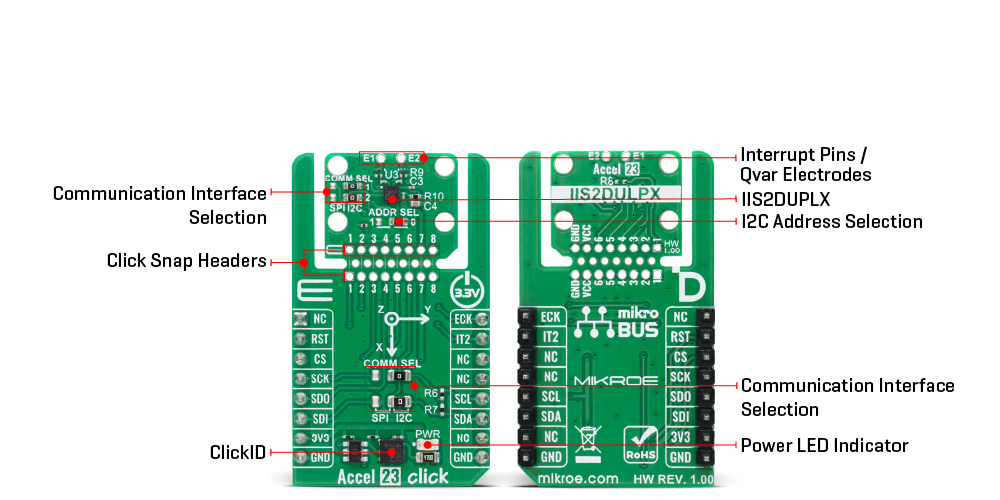
This Click board™ is designed in a unique format supporting the newly introduced MIKROE feature called "Click Snap." Unlike the standardized version of Click boards, this feature allows the main sensor/IC/module area to become movable by breaking the PCB, opening up many new possibilities for implementation. Thanks to the Snap feature, the IIS2DULPX can operate autonomously by accessing its signals directly on the pins marked 1-8. Additionally, the Snap part includes a specified and fixed screw hole position, enabling users to secure the Snap board in their desired location.
This board supports communication with the host MCU through either SPI (maximum clock frequency of 10MHz) or I2C (maximum clock frequency of 1MHz) interfaces, with I2C being the default option. The communication interface is selected by adjusting the COMM SEL jumper to the desired position. To enhance flexibility, particularly with the detachable Snap section of the Click Snap format, an additional COMM SEL jumpers are available. These jumpers functions the same as the COMM SEL, allowing for independent communication interface selection when the Snap section is used independently. To ensure proper functionality, all COMM jumpers must be set to the same interface. For those using the I2C interface, the board also provides an ADDR SEL jumper, enabling users to configure the I2C address as needed for their specific application.
This Click board™ can be operated only with a 3.3V logic voltage level. The board must perform appropriate logic voltage level conversion before using MCUs with different logic levels. It also comes equipped with a library containing functions and example code that can be used as a reference for further development.
Click Snap is an innovative feature of our standardized Click add-on boards, designed to bring greater flexibility and optimize your prototypes. By simply snapping the PCB along predefined lines, you can easily detach the main sensor/IC/module area, reducing the overall size, weight, and power consumption - ideal for the final phase of prototyping. For more details about Click Snap, visit the official page dedicated to this feature.
Type
Acceleration,Motion
Applications
Ideal for industrial IoT, factory automation, asset tracking, portable healthcare, robotics, and motion-activated functions
On-board modules
IIS2DULPX - intelligent ultra low-power accelerometer for industrial applications from STMicroelectronics
Key Features
Intelligent ultra low-power 3-axis digital accelerometer, always-on antialiasing filtering, programmable finite state machine, embedded machine learning core with adaptive self-configuration, analog hub with Qvar sensing channel, four operating modes, external clock input for synchronization, SPI and I2C communication interfaces, Click Snap format, and more
Interface
I2C,I3C,SPI
Feature
Click Snap,ClickID
Compatibility
mikroBUS™
Click board size
M (42.9 x 25.4 mm)
Input Voltage
1.8V,3.3V
This table shows how the pinout on Accel 23 Click corresponds to the pinout on the mikroBUS™ socket (the latter shown in the two middle columns).
| Notes | Pin | Pin | Notes | ||||
|---|---|---|---|---|---|---|---|
| NC | 1 | AN | PWM | 16 | ECK | External Synchronization Clock | |
| ID SEL | RST | 2 | RST | INT | 15 | IT2 | Interrupt |
| SPI Select / ID COMM | CS | 3 | CS | RX | 14 | NC | |
| SPI Clock | SCK | 4 | SCK | TX | 13 | NC | |
| SPI Data OUT | SDO | 5 | MISO | SCL | 12 | SCL | I2C Clock |
| SPI Data IN | SDI | 6 | MOSI | SDA | 11 | SDA | I2C Data |
| Power Supply | 3.3V | 7 | 3.3V | 5V | 10 | NC | |
| Ground | GND | 8 | GND | GND | 9 | GND | Ground |
| Label | Name | Default | Description |
|---|---|---|---|
| LD1 | PWR | - | Power LED Indicator |
| JP1-JP2 | COMM SEL | Right | mikroBUS-Side Communication Interface Selection SPI/I2C: Left position SPI, Right position I2C |
| JP3-JP4 | COMM SEL | Right | Snap-Side Communication Interface Selection SPI/I2C: Left position SPI, Right position I2C |
| JP5 | ADDR SEL | Right | I2C Address Selection 1/0: Left position 1, Right position 0 |
| Description | Min | Typ | Max | Unit |
|---|---|---|---|---|
| Supply Voltage | - | 3.3 | - | V |
| Acceleration Range | ±2 | - | ±16 | g |
| Sensitivity | 0.061 | - | 0.488 | mg/digit |
Accel 23 Click demo application is developed using the NECTO Studio, ensuring compatibility with mikroSDK's open-source libraries and tools. Designed for plug-and-play implementation and testing, the demo is fully compatible with all development, starter, and mikromedia boards featuring a mikroBUS™ socket.
Example Description
This example demonstrates the use of the Accel 23 Click board by reading acceleration and temperature data from the onboard 3-axis accelerometer. The measured values are displayed via the UART terminal.
Key Functions
accel23_cfg_setup This function initializes Click configuration structure to initial values.accel23_init This function initializes all necessary pins and peripherals used for this Click board.accel23_default_cfg This function executes a default configuration of Accel 23 Click board.accel23_get_data This function retrieves acceleration and temperature data from the device.Application Init
Initializes the logger and the Click board and applies the default configuration.
Application Task
Reads the acceleration values in X, Y, and Z axis as well as the internal temperature, then displays the results on the UART terminal.
Application Output
This Click board can be interfaced and monitored in two ways:
Additional Notes and Information
The complete application code and a ready-to-use project are available through the NECTO Studio Package Manager for direct installation in the NECTO Studio. The application code can also be found on the MIKROE GitHub account.
NOTE: Please be advised that any peripheral devices or accessories shown connected to the Click board™ are not included in the package. Check their availability in our shop or in the YMAN section below.

$1.20

$1.74

$3.00

$1.20

$889.00

$95.00

$549.00

$299.00

$29.00

$29.00

$3.30

$3.60

$119.00

$449.00

$349.00

$349.00

$349.00

$299.00

$269.00

$249.00

$209.00
