


OFF
GO LOCAL
| Company | Stock | Price |
|---|---|---|


MIKROE-6827
21 g
Status:
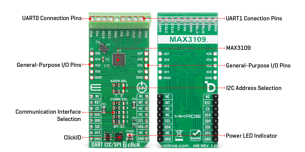
UART I2C/SPI 2 Click is a compact add-on board that provides a high-performance dual UART interface for bridging SPI or I2C processor buses to asynchronous serial communication standards such as RS-232, RS-485, or IrDA. It is based on the MAX3109, a dual UART with 128-word receive and transmit FIFOs from Analog Devices, supporting data rates up to 24Mbps. The board features automatic hardware and software flow control, programmable baud-rate generation, logic-level translation, and half-duplex transceiver control for protocols like PROFIBUS DP. It also includes reset and interrupt pins, and two unpopulated GPIO headers offering user-configurable I/O or interrupt functionality. UART I2C/SPI 2 Click is ideal for handheld devices, power meters, PLCs, medical and POS systems, and building automation applications requiring reliable high-speed serial connectivity.
UART I2C/SPI 2 Click is fully compatible with the mikroBUS™ socket and can be used on any host system supporting the mikroBUS™ standard. It comes with the mikroSDK open-source libraries, offering unparalleled flexibility for evaluation and customization. What sets this Click board™ apart is the groundbreaking ClickID feature, enabling your host system to automatically detect and identify this add-on board.
This product is no longer in stock
Availability date:
OFF
| Company | Stock | Price |
|---|---|---|
UART I2C/SPI 2 Click based on the MAX3109, a dual universal asynchronous receiver-transmitter (UART) from Analog Devices that features 128-word receive and transmit FIFOs and supports both SPI and I2C communication with the host microcontroller. The board bridges SPI/MICROWIRE or I2C processor buses to asynchronous serial interfaces such as RS-232, RS-485, or IrDA, ensuring reliable and high-speed data transfer. The MAX3109 integrates an SIR- and MIR-compliant IrDA encoder/decoder and includes line noise indication to maintain data link integrity. It offers 2x and 4x rate modes, allowing data rates up to 24Mbps, while its internal phase-locked loop (PLL) and fractional baud-rate generators enable flexible baud-rate programming and reference clock selection.
Independent logic-level translation between the controller and transceiver interfaces allows simple connection to microcontrollers, FPGAs, and transceivers operating at different supply voltages. With automatic hardware and software flow control and selectable FIFO interrupt triggering, the MAX3109 offloads low-level communication tasks from the host controller, improving system efficiency. Additionally, it features automatic half-duplex transceiver control with programmable setup and hold times, making it suitable for high-speed industrial protocols like PROFIBUS DP.
The large 128-word FIFOs provide advanced buffer management, reducing processor overhead and ensuring smooth data flow even in demanding environments. Thanks to its versatile architecture, UART I2C/SPI 2 Click is ideal for use in handheld devices, power meters, programmable logic controllers (PLCs), medical systems, point-of-sales equipment, and HVAC or building automation systems where reliable, high-speed serial communication is required.
The host MCU communcates with the MAX3109 through the SPI or I2C interface, with a maximum frequency of 1MHz for I2C and 26MHz for SPI communication. The selection is made by positioning SMD jumpers labeled COMM SEL appropriately. Note that all the jumpers' positions must be on the same side, or the Click board™ may become unresponsive. While the I2C interface is selected, the MAX3109 allows the least significant bit (LSB) of its I2C address to be chosen using the SMD jumpers labeled ADDR SEL.
Besides interface pins, the board also includes RST pin for resetting the MAX3109, and INT pin as active-low open-drain interrupt output. This pin is is asserted when an interrupt is pending. The UART I2C/SPI 2 Click also includes two unpopulated 1x5 header connectors that expose a set of general-purpose input/output (GPIO) pins from the MAX3109 IC. These GPIOs are fully user-programmable, offering flexible configuration options to suit various application requirements. Each pin can be individually set as an input or output, with selectable push-pull or open-drain operation modes, allowing adaptation to different logic levels and external circuit conditions. Furthermore, the GPIOs can function as external event-driven interrupt sources, enabling efficient handling of asynchronous system events without constant polling from the host controller.
This Click board™ can be operated only with a 3.3V logic voltage level. The board must perform appropriate logic voltage level conversion before using MCUs with different logic levels. It also comes equipped with a library containing functions and example code that can be used as a reference for further development.
Type
RS232
Applications
Ideal for handheld devices, power meters, PLCs, medical and POS systems, and building automation applications requiring reliable high-speed serial connectivity
On-board modules
MAX3109 - dual serial UART with 128-word FIFOs from Analog Devices
Key Features
Dual UART interface with 128-word receive and transmit FIFOs, data rates up to 24Mbps with 2x and 4x rate modes, integrated SIR/MIR-compliant IrDA encoder/decoder, line noise indication for data integrity, programmable baud-rate generator with PLL and fractional clock selection, automatic hardware and software flow control, selectable FIFO interrupt triggering, and more
Interface
GPIO,I2C,SPI,UART
Feature
ClickID
Compatibility
mikroBUS™
Click board size
L (57.15 x 25.4 mm)
Input Voltage
3.3V
This table shows how the pinout on UART I2C/SPI 2 Click corresponds to the pinout on the mikroBUS™ socket (the latter shown in the two middle columns).
| Notes | Pin | Pin | Notes | ||||
|---|---|---|---|---|---|---|---|
| NC | 1 | AN | PWM | 16 | NC | ||
| Reset / ID SEL | RST | 2 | RST | INT | 15 | INT | Interrupt |
| SPI Select / ID COMM | CS | 3 | CS | RX | 14 | NC | |
| SPI Clock | SCK | 4 | SCK | TX | 13 | NC | |
| SPI Data OUT | SDO | 5 | MISO | SCL | 12 | SCL | I2C Clock |
| SPI Data IN | SDI | 6 | MOSI | SDA | 11 | SDA | I2C Data |
| Power Supply | 3.3V | 7 | 3.3V | 5V | 10 | NC | |
| Ground | GND | 8 | GND | GND | 9 | GND | Ground |
| Label | Name | Default | Description |
|---|---|---|---|
| LD1 | PWR | - | Power LED Indicator |
| JP1-JP5 | COMM SEL | Left | Communication Interface Selection SPI/I2C: Left position SPI , Right position I2C |
| JP6-JP7 | ADDR SEL | Right | I2C Address Selection 1/0: Left position 1, Right position 0 |
| Description | Min | Typ | Max | Unit |
|---|---|---|---|---|
| Supply Voltage | - | 3.3 | - | V |
| UART Data Rate | - | - | 24 | Mbps |
| SPI Clock Frequency | - | - | 26 | MHz |
| I2C Clock Frequency | - | - | 1 | MHz |
UART I2C SPI 2 Click demo application is developed using the NECTO Studio, ensuring compatibility with mikroSDK's open-source libraries and tools. Designed for plug-and-play implementation and testing, the demo is fully compatible with all development, starter, and mikromedia boards featuring a mikroBUS™ socket.
Example Description
This example demonstrates the use of the UART I2C SPI 2 Click board. It sends a predefined demo message to both UART0 and UART1 interfaces, then reads back any received data and logs the results on the USB UART.
Key Functions
uarti2cspi2_cfg_setup This function initializes Click configuration structure to initial values.uarti2cspi2_init This function initializes all necessary pins and peripherals used for this Click board.uarti2cspi2_default_cfg This function executes a default configuration of UART I2C SPI 2 Click board.uarti2cspi2_read_reg This function reads a single byte of data from the selected register address.uarti2cspi2_read_data This function reads a block of data from the receive buffer.uarti2cspi2_write_data This function writes a block of data to the transmit buffer.Application Init
Initializes the logger and UART I2C SPI 2 Click, and applies the default configuration which sets the UART0 to 115200-8N1 and UART1 to 9600-8N1.
Application Task
Alternately selects UART0 and UART1, sends the demo message, reads back data from the RX FIFO, and logs the transmitted and received strings every second.
Application Output
This Click board can be interfaced and monitored in two ways:
Additional Notes and Information
The complete application code and a ready-to-use project are available through the NECTO Studio Package Manager for direct installation in the NECTO Studio. The application code can also be found on the MIKROE GitHub account.
NOTE: Please be advised that any peripheral devices or accessories shown connected to the Click board™ are not included in the package. Check their availability in our shop or in the YMAN section below.

$889.00

$95.00

$549.00

$299.00

$29.00

$29.00

$6.59

$3.60

$119.00

$449.00

$349.00

$349.00

$349.00

$299.00

$269.00

$249.00

$209.00
