


OFF
GO LOCAL
| Company | Stock | Price |
|---|---|---|


MIKROE-6778
21 g
Status:
2-Wire SPI ISO Click is a compact add-on board that provides a galvanically isolated communication bridge between devices operating in different voltage domains, enabling SPI data transfer across isolation barriers. It is based on the L9963T, an automotive general-purpose SPI to isolated SPI transceiver from STMicroelectronics. The board allows conversion between a standard 4-wire SPI and a proprietary 2-wire isolated SPI interface, supporting both transformer and capacitive isolation. It can be configured as either Master or Slave, with support for SPI frames from 8 to 64 bits, clock frequencies up to 10MHz in Slave mode, and programmable clock options in Master mode. The isolated side features selectable operating speeds of 333kbps or 2.66Mbps, while internal buffering ensures smooth data flow across asynchronous domains. This Click board™ is ideal for automotive 48V and high-voltage systems, backup energy storage, UPS, industrial networks, remote sensors, and portable equipment.
2-Wire SPI ISO Click is fully compatible with the mikroBUS™ socket and can be used on any host system supporting the mikroBUS™ standard. It comes with the mikroSDK open-source libraries, offering unparalleled flexibility for evaluation and customization. What sets this Click board™ apart is the groundbreaking ClickID feature, enabling your host system to automatically detect and identify this add-on board.
This product is no longer in stock
Availability date:
OFF
| Company | Stock | Price |
|---|---|---|
2-Wire SPI ISO Click is based on the L9963T, an automotive general-purpose SPI to isolated SPI transceiver from STMicroelectronics that provides a galvanically isolated communication bridge between devices operating in different voltage domains. The L9963T is designed to transfer data from a classical 4-wire SPI interface to a proprietary 2-wire isolated interface and back, ensuring data exchange in environments where galvanic isolation is required. It supports both transformer and capacitive isolation, since the generated isolated signal is compatible with both decoupling technologies. This Click board™ is ideal for automotive 48V and high-voltage systems, backup energy storage and UPS applications, industrial communication networks, portable and semi-portable devices, and remote sensors, providing an isolated SPI communication link for demanding embedded applications.
The L9963T can be configured either as a Slave or a Master mode of the SPI bus by placing MODE SEL jumpers in the proper positions and supports any SPI frame length from 8 to 64 bits, transferring data transparently without performing protocol checks. In Slave mode, the SPI interface can operate at up to 10MHz, while in Master mode the clock frequency can be selected among 250kHz, 1MHz, 4MHz, or 8MHz. On the isolated SPI side, two operating modes are available: a low-speed mode at 333kbps and a high-speed mode at 2.66Mbps, selectable via the FREQ SEL jumper.
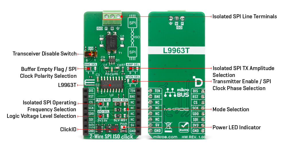
The device internally manages the asynchronicity between both sides, enabling the use of all frequency configurations across the two SPI domains. To accommodate timing differences and ensure smooth data flow, the L9963T integrates a buffer with 3 slots for frames received on the SPI port and 20 slots for frames received on the isolated SPI port, decoupling the two clock domains. The board also features a DIS switch that allows the user to disable the transmitter and place the device into a low-power mode when set to position 1, or keep it in normal operating mode when set to position 0. A set of jumpers provides additional flexibility: BNE SEL controls the SDO Buffer Not Empty flag and allows SPI clock polarity (CPOL) selection, AMP SEL selects the isolated SPI transmit amplitude and threshold between low and high, and TxEN SEL enables the transmitter or selects the SPI clock phase (CPHA).
This Click board™ can operate with either 3.3V or 5V logic voltage levels selected via the VIO SEL jumper. This way, both 3.3V and 5V capable MCUs can use the communication lines properly. Also, this Click board™ comes equipped with a library containing easy-to-use functions and an example code that can be used as a reference for further development.
Type
Isolators,SPI
Applications
Ideal for automotive 48V and high-voltage systems, backup energy storage, UPS, industrial networks, remote sensors, and portable equipment
On-board modules
L9963T - automotive general purpose SPI to isolated SPI transceiver from STMicroelectronics
Key Features
Conversion between 4-wire SPI and proprietary 2-wire isolated SPI interface, support for transformer and capacitive isolation, configurable Master or Slave operation, support for SPI frames from 8 to 64 bits, 10MHz SPI operation in Slave mode, programmable SPI Master clock options, isolated SPI operating speeds, internal buffering with 3 slots on the SPI side and 20 slots on the isolated SPI side, and more
Interface
SPI
Feature
ClickID
Compatibility
mikroBUS™
Click board size
L (57.15 x 25.4 mm)
Input Voltage
3.3V or 5V
This table shows how the pinout on 2-Wire SPI ISO Click corresponds to the pinout on the mikroBUS™ socket (the latter shown in the two middle columns).
| Notes | Pin | Pin | Notes | ||||
|---|---|---|---|---|---|---|---|
| Transceiver Disable | DIS | 1 | AN | PWM | 16 | TEN | Transmitter Enable / SPI Clock Phase |
| ID SEL | RST | 2 | RST | INT | 15 | BNE | Buffer Flag / SPI Clock Polarity |
| SPI Select / ID COMM | CS | 3 | CS | RX | 14 | NC | |
| SPI Clock | SCK | 4 | SCK | TX | 13 | NC | |
| SPI Data OUT | SDO | 5 | MISO | SCL | 12 | NC | |
| SPI Data IN | SDI | 6 | MOSI | SDA | 11 | NC | |
| Power Supply | 3.3V | 7 | 3.3V | 5V | 10 | 5V | Power Supply |
| Ground | GND | 8 | GND | GND | 9 | GND | Ground |
| Label | Name | Default | Description |
|---|---|---|---|
| LD1 | PWR | - | Power LED Indicator |
| JP1 | VIO SEL | Left | Logic Voltage Level Selection 3V3/5V: Left position 3V3, Right position 5V |
| JP2/JP7-JP8 | MODE SEL | Left | Mode Selection SLV/MST: Left position SLV, Right position MST |
| JP3 | FREQ SEL | Left | Isolated SPI Operating Frequency Selection 0/1: Left position 0, Right position 1 |
| JP4 | AMP SEL | Left | Isolated SPI TX Amplitude Selection 0/1: Left position 0, Right position 1 |
| JP5 | TxEN SEL | Right | Transmitter Enable / SPI Clock Phase Selection 0/1: Left position 0, Right position 1 |
| JP6 | BNE SEL | Left | SDO Buffer Empty Flag / SPI Clock Polarity Selection 1/0: Left position 1, Right position 0 |
| SW1 | DIS | Left | Transceiver Disable Switch |
| Description | Min | Typ | Max | Unit |
|---|---|---|---|---|
| Supply Voltage | 3.3 | - | 5 | V |
| SPI Clock Frequency (Slave mode) | - | - | 10 | MHz |
| SPI Clock Frequency (Master mode) | 0.25 | - | 8 | MHz |
| Isolated SPI Speed | 0.333 | - | 2.66 | Mbps |
| SPI Frame Length | 8 | - | 64 | bits |
2-Wire SPI ISO Click demo application is developed using the NECTO Studio, ensuring compatibility with mikroSDK's open-source libraries and tools. Designed for plug-and-play implementation and testing, the demo is fully compatible with all development, starter, and mikromedia boards featuring a mikroBUS™ socket.
Example Description
This example demonstrates the use of a 2-Wire SPI ISO Click board by showing the communication between the two Click boards (Slave and Master). That is performed by sending commands to a 2-Wire SPI ISO Click (Slave) to read the device ID of a Accel 22 Click board connected to the 2-Wire SPI ISO Click (Master).
Key Functions
c2wirespiiso_cfg_setup Config Object Initialization function.c2wirespiiso_init Initialization function.c2wirespiiso_default_cfg Click Default Configuration function.c2wirespiiso_write This function writes a desired number of data bytes by using SPI serial interface.c2wirespiiso_read This function reads a desired number of data bytes by using SPI serial interface.c2wirespiiso_get_bne_pin This function returns the RX buffer not empty (BNE) pin logic state.Application Init
Initializes the driver and performs the Click default configuration.
Application Task
Reads and checks the device ID of a Accel 22 Click board connected to the 2-Wire SPI ISO (Master) Click, and displays the results on the USB UART approximately once per second.
Application Output
This Click board can be interfaced and monitored in two ways:
Additional Notes and Information
The complete application code and a ready-to-use project are available through the NECTO Studio Package Manager for direct installation in the NECTO Studio. The application code can also be found on the MIKROE GitHub account.
NOTE: Please be advised that any peripheral devices or accessories shown connected to the Click board™ are not included in the package. Check their availability in our shop or in the YMAN section below.

$889.00

$95.00

$549.00

$299.00

$29.00

$29.00

$6.59

$3.60

$119.00

$349.00

$349.00

$299.00

$449.00

$349.00

$269.00

$249.00

$209.00
