


OFF
GO LOCAL
| Company | Stock | Price |
|---|---|---|


MIKROE-6749
18 g
Status:
6DOF IMU 28 Click is a compact add-on board designed for multi-axis motion sensing and intelligent event detection in embedded applications. It is based on the LSM6DSV320X, a 6-axis IMU with low-g and high-g accelerometers and a digital gyroscope featuring embedded intelligence from STMicroelectronics. This sensor combines a high-g channel for shock detection, dual event-detection interrupts, and advanced edge-processing capabilities such as a machine learning core, finite state machine, and adaptive self-configuration to offload algorithms from the host MCU and reduce power consumption. It supports SPI or I2C communication with selectable addresses, incorporates the innovative Click Snap format for detachable operation, and offers flexibility through auxiliary I3C/SPI interfaces for connecting external sensors or expanding its functionality. 6DOF IMU 28 Click is ideal for IoT and connected devices, asset tracking, wearables, smartphones, AR/VR/MR systems, vibration monitoring, and car crash or shock detection applications.
6DOF IMU 28 Click is fully compatible with the mikroBUS™ socket and can be used on any host system supporting the mikroBUS™ standard. It comes with the mikroSDK open-source libraries, offering unparalleled flexibility for evaluation and customization. What sets this Click board™ apart is the groundbreaking ClickID feature, enabling your host system to automatically detect and identify this add-on board, alongside a Click Snap feature introducing a new level of flexibility and ease of use.
This product is no longer in stock
Availability date:
OFF
| Company | Stock | Price |
|---|---|---|
6DOF IMU 28 Click is based on the LSM6DSV320X, a 6-axis IMU that combines a low-g and high-g accelerometer with a digital gyroscope and advanced embedded intelligence from STMicroelectronics. This sensor integrates a 3-axis digital low-g accelerometer up to ±16g, a 3-axis digital high-g accelerometer up to ±320g, and a 3-axis digital gyroscope, forming a unique quad-channel architecture that processes acceleration and angular rate data on four separate channels: user interface, optical image stabilization (OIS), electronic image stabilization (EIS), and high-g accelerometer data – each with its own configuration, processing, and filtering. By embedding a dedicated high-g sensor channel, the LSM6DSV320X enables high-g shock and impact detection, making it ideal for car crash detection, concussion monitoring, and extreme sports applications.
The LSM6DSV320X pushes edge computing further with its integrated finite state machine (FSM) and machine learning core (MLC), which allow configurable motion tracking, context awareness, and exportable AI features without relying on the host processor. Its adaptive self-configuration (ASC) feature dynamically reconfigures the device in real time based on detected motion patterns or decision tree outputs from the MLC, enhancing responsiveness and lowering power consumption for IoT and wearable designs. This combination of high-resolution sensing, embedded intelligence, and dedicated high-g detection opens up a broad range of applications, including IoT and connected devices, asset tracking, smartphones and handhelds, car crash and shock detection, wearables, gesture recognition and motion tracking, augmented/virtual/mixed reality experiences, indoor navigation, vibration monitoring and compensation, as well as advanced camera stabilization for EIS and OIS.
This Click board™ is designed in a unique format supporting the newly introduced MIKROE feature called "Click Snap." Unlike the standardized version of Click boards, this feature allows the main sensor/IC/module area to become movable by breaking the PCB, opening up many new possibilities for implementation. Thanks to the Snap feature, the LSM6DSV320X can operate autonomously by accessing its signals directly on the pins marked 1-8. Additionally, the Snap part includes a specified and fixed screw hole position, enabling users to secure the Snap board in their desired location.
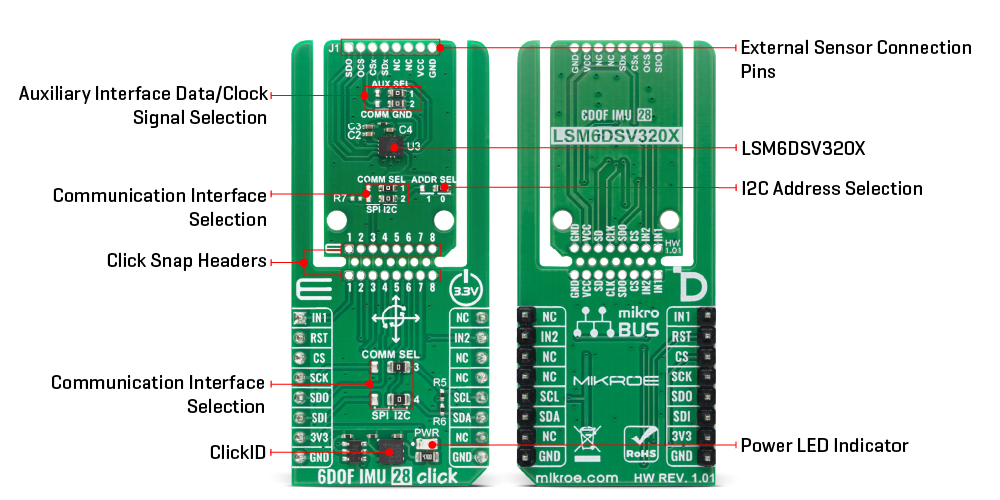
This board supports communication with the host MCU through either SPI (maximum clock frequency of 10MHz) or I2C (maximum clock frequency of 1MHz) interfaces, with I2C being the default option. The communication interface is selected by adjusting the COMM SEL jumper to the desired position. To enhance flexibility, particularly with the detachable Snap section of the Click Snap format, an additional COMM SEL jumpers are available. These jumpers functions the same as the COMM SEL, allowing for independent communication interface selection when the Snap section is used independently. To ensure proper functionality, all COMM jumpers must be set to the same interface. For those using the I2C interface, the board also provides an ADDR SEL jumper, enabling users to configure the I2C address as needed for their specific application.
The LSM6DSV320X enhances intelligent motion sensing with its dual event-detection interrupt pins (IN1 and IN2), enabling recognition of a wide range of movement and context-awareness events such as free-fall detection, 6D orientation, single and double-click actions, activity or inactivity status, stationary or motion detection, and wake-up triggers. This Click board™ also provides hardware flexibility through its J1 header, allowing the LSM6DSV320X to connect to external sensors and expand its functionality by adding features such as a sensor hub, auxiliary SPI, and more.
In this configuration, the board supports the use of either auxiliary I3C or auxiliary SPI (3- or 4-wire) for transferring measured acceleration and angular rate data. Within the Snap section, an AUX SEL jumper is available to select the auxiliary interface data and clock signals, automatically routing the appropriate lines depending on whether the auxiliary SPI or I3C interface is active. The OCS pin on the J1 header serves as the auxiliary interface selector: when driven high, the pin places the auxiliary SPI in idle mode and enables the I3C interface, while when driven low, it activates auxiliary SPI communication and disables the I3C interface.
This Click board™ can be operated only with a 3.3V logic voltage level. The board must perform appropriate logic voltage level conversion before using MCUs with different logic levels. It also comes equipped with a library containing functions and example code that can be used as a reference for further development.
Click Snap is an innovative feature of our standardized Click add-on boards, designed to bring greater flexibility and optimize your prototypes. By simply snapping the PCB along predefined lines, you can easily detach the main sensor/IC/module area, reducing the overall size, weight, and power consumption - ideal for the final phase of prototyping. For more details about Click Snap, visit the official page dedicated to this feature.
Type
Motion
Applications
Ideal for IoT and connected devices, asset tracking, wearables, smartphones, AR/VR/MR systems, vibration monitoring, and car crash or shock detection applications
On-board modules
LSM6DSV320X - 6-axis IMU high-g accelerometer, embedded AI, and sensor fusion from STMicroelectronics
Key Features
Low-g and high-g 3-axis accelerometers up to ±16g and ±320g, 3-axis digital gyroscope, quad-channel architecture for separate processing of user interface, OIS, EIS and high-g data, channel for shock and impact detection, integrated finite state machine and machine learning core for motion tracking and context awareness, Click Snap format, and more
Interface
I2C,I3C,SPI
Feature
Click Snap,ClickID
Compatibility
mikroBUS™
Click board size
L (57.15 x 25.4 mm)
Input Voltage
1.8V,3.3V
This table shows how the pinout on 6DOF IMU 28 Click corresponds to the pinout on the mikroBUS™ socket (the latter shown in the two middle columns).
| Notes | Pin | Pin | Notes | ||||
|---|---|---|---|---|---|---|---|
| Interrupt 1 | IN1 | 1 | AN | PWM | 16 | NC | |
| ID SEL | RST | 2 | RST | INT | 15 | IN2 | Interrupt 2 |
| SPI Select / ID COMM | CS | 3 | CS | RX | 14 | NC | |
| SPI Clock | SCK | 4 | SCK | TX | 13 | NC | |
| SPI Data OUT | SDO | 5 | MISO | SCL | 12 | SCL | I2C Clock |
| SPI Data IN | SDI | 6 | MOSI | SDA | 11 | SDA | I2C Data |
| Power Supply | 3.3V | 7 | 3.3V | 5V | 10 | 5V | Power Supply |
| Ground | GND | 8 | GND | GND | 9 | GND | Ground |
| Label | Name | Default | Description |
|---|---|---|---|
| LD1 | PWR | - | Power LED Indicator |
| JP1/JP4 | COMM SEL | Right | Snap-Side Communication Interface Selection SPI/I2C: Left position SPI, Right position I2C |
| JP2-JP3 | COMM SEL | Right | mikroBUS-Side Communication Interface Selection SPI/I2C: Left position SPI, Right position I2C |
| JP5 | ADDR SEL | Right | I2C Address Selection 1/0: Left position 1, Right position 0 |
| JP6-JP7 | AUX SEL | Right | Auxiliary Interface Data/Clock Selection COMM/GND: Left position COMM , Right position GND |
| Description | Min | Typ | Max | Unit |
|---|---|---|---|---|
| Supply Voltage | - | 1.8 / 3.3 | - | V |
| Accelerometer Measurement Range (low-g) | ±2 | - | ±16 | g |
| Accelerometer Measurement Range (high-g) | - | - | ±320 | g |
| Gyroscope Measurement Range | ±125 | - | ±2000 | dps |
| Accelerometer Sensitivity (low-g) | 0.061 | - | 0.244 | mg/LSB |
| Accelerometer Sensitivity (high-g) | 0.976 | - | 10.417 | mg/LSB |
| Gyroscope Sensitivity | 8.75 | - | 140 | mdps/LSB |
6DOF IMU 28 Click demo application is developed using the NECTO Studio, ensuring compatibility with mikroSDK's open-source libraries and tools. Designed for plug-and-play implementation and testing, the demo is fully compatible with all development, starter, and mikromedia boards featuring a mikroBUS™ socket.
Example Description
This example demonstrates the use of 6DOF IMU 28 Click board by reading and displaying the accelerometer and gyroscope data (X, Y, and Z axis) as well as a temperature measurement in degrees Celsius.
Key Functions
c6dofimu28_cfg_setup This function initializes Click configuration structure to initial values.c6dofimu28_init This function initializes all necessary pins and peripherals used for this Click board.c6dofimu28_default_cfg This function executes a default configuration of 6DOF IMU 28 Click board.c6dofimu28_get_int1_pin This function returns the interrupt 1 pin logic state.c6dofimu28_get_data This function reads the accelerometer, gyroscope, and temperature measurement data.Application Init
Initializes the driver and performs the Click default configuration.
Application Task
Waits for a data ready indication and then reads the accelerometer, gyroscope, and temperature measurements. The results are displayed on the USB UART at 7.5 Hz output data rate.
Application Output
This Click board can be interfaced and monitored in two ways:
Additional Notes and Information
The complete application code and a ready-to-use project are available through the NECTO Studio Package Manager for direct installation in the NECTO Studio. The application code can also be found on the MIKROE GitHub account.
NOTE: Please be advised that any peripheral devices or accessories shown connected to the Click board™ are not included in the package. Check their availability in our shop or in the YMAN section below.

$1.20

$1.74

$3.00

$1.20

$889.00

$95.00

$549.00

$299.00

$29.00

$29.00

$6.59

$3.60

$119.00

$449.00

$349.00

$349.00

$349.00

$299.00

$269.00

$249.00

$209.00
