


OFF
GO LOCAL
| Company | Stock | Price |
|---|---|---|


MIKROE-6747
18 g
Status:
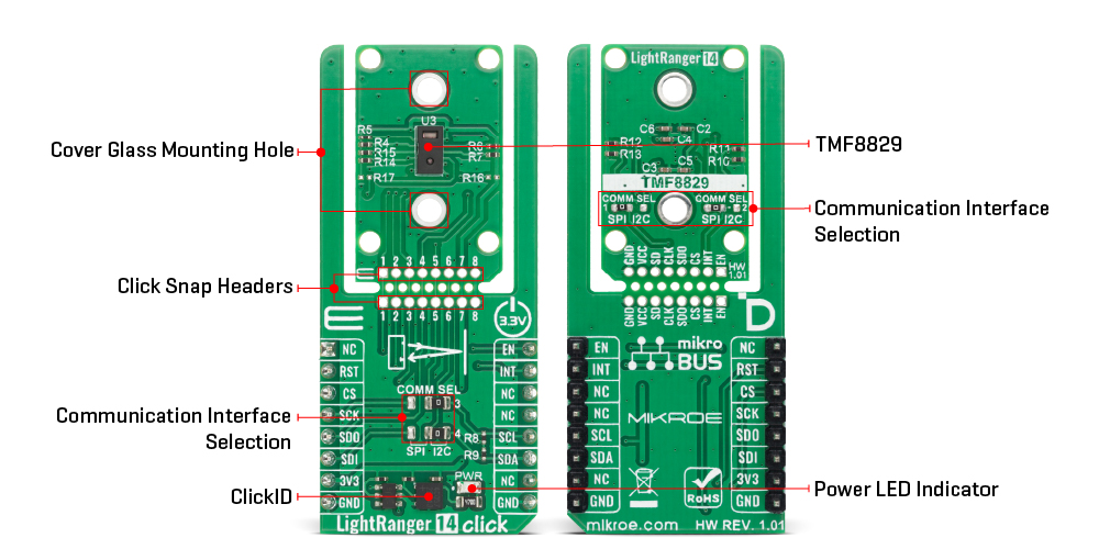
LightRanger 14 Click is a compact add-on board that provides high-precision distance and depth measurement capabilities using direct time-of-flight (dToF) technology. It is based on the TMF8829, a high-performance multi-zone dToF sensor from ams OSRAM featuring integrated SPAD detection, time-to-digital conversion, and histogram processing. It supports configurable depth map resolutions of 8x8, 16x16, 32x32, and 48x32 zones, offering detection ranges from 10mm to 11.000mm with fine 0.25mm resolution and an 80° field of view. Equipped with an integrated VCSEL and multi-lens-array (MLA), it ensures uniform illumination and robust performance even under challenging optical conditions. The board features both I2C (I3C-compatible) and SPI interfaces and includes pins for control and interrupt signaling. This Click board™ is ideal for applications such as laser autofocus (LDAF), robotics, SLAM, gesture recognition, and people counting systems.
LightRanger 14 Click is fully compatible with the mikroBUS™ socket and can be used on any host system supporting the mikroBUS™ standard. It comes with the mikroSDK open-source libraries, offering unparalleled flexibility for evaluation and customization. What sets this Click board™ apart is the groundbreaking ClickID feature, enabling your host system to automatically detect and identify this add-on board, alongside a Click Snap feature introducing a new level of flexibility and ease of use.
This product is no longer in stock
Availability date:
OFF
| Company | Stock | Price |
|---|---|---|
LightRanger 14 Click is based on the TMF8829, a high-performance direct time-of-flight (dToF) sensor from ams OSRAM capable of providing depth resolution up to 48x32 zones with an exceptionally wide field of view of 80° (diagonal, 4:3 aspect ratio). The TMF8829 combines advanced SPAD detection, time-to-digital conversion, and histogram processing technologies within a single package, allowing precise distance measurements from as close as 10mm up to 11.000mm. This sensor delivers outstanding signal-to-noise ratio, high dynamic range, and immunity to multi-path reflections, ensuring stable and reliable operation even in demanding optical environments. The LightRanger 14 Click is an ideal solution for both industrial and consumer-grade distance and depth measurement systems including laser detect autofocus (LDAF), depth mapping for bokeh effects, simultaneous localization and mapping (SLAM), robotic automation tasks such as obstacle avoidance, cliff detection, and room scanning, as well as people counting and advanced gesture recognition.
Featuring configurable output resolutions of 8x8, 16x16, 32x32, and 48x32 depth maps, the TMF8829 can adapt to a wide range of applications from long-range sensing to high-resolution depth imaging while maintaining accuracy with a minimum measurable distance of just 1cm and a fine resolution of 0.25mm. The embedded Vertical Cavity Surface Emitting Laser (VCSEL) and multi-lens-array (MLA) expand the field of illumination, enabling efficient and uniform projection across the entire sensing area. All essential signal processing is performed internally, offloading the host system and providing direct access to processed distance data, confidence levels, signal amplitudes, and ambient light information.
This Click board™ is designed in a unique format supporting the newly introduced MIKROE feature called "Click Snap." Unlike the standardized version of Click boards, this feature allows the main sensor/IC/module area to become movable by breaking the PCB, opening many new possibilities for implementation. Thanks to the Snap feature, the TMF8829 can operate autonomously by accessing its signals directly on the pins marked 1-8. Additionally, the Snap part includes a specified and fixed screw hole position, enabling users to secure the Snap board in their desired location.
The TMF8829 supports both I2C (I3C-compatible) and SPI interfaces, selectable via COMM SEL jumpers, offering fast and flexible communication for raw data streaming and algorithmic results. It can also deliver full histogram data at high speed, making it suitable for AI-enabled applications that rely on machine learning or computer vision for environmental awareness. The sensor’s dToF architecture supports detection of up to four objects per depth point simultaneously and maintains high accuracy even when the sensor cover glass is smudged or contaminated. Besides interface pins, the board also includes an EN pin for device enable control and an INT pin for interrupt signaling from the sensor, allowing straightforward system integration and event-driven operation.
This Click board™ can be operated only with a 3.3V logic voltage level. The board must perform appropriate logic voltage level conversion before using MCUs with different logic levels. It also comes equipped with a library containing functions and example code that can be used as a reference for further development.
Click Snap is an innovative feature of our standardized Click add-on boards, designed to bring greater flexibility and optimize your prototypes. By simply snapping the PCB along predefined lines, you can easily detach the main sensor/IC/module area, reducing the overall size, weight, and power consumption - ideal for the final phase of prototyping. For more details about Click Snap, visit the official page dedicated to this feature.
Type
Optical
Applications
Ideal for applications such as laser autofocus (LDAF), robotics, SLAM, gesture recognition, and people counting systems
On-board modules
TMF8829 - direct time-of-flight (dToF) sensor with a resolution of up to 48x32 from ams OSRAM
Key Features
High-resolution direct time-of-flight (dToF) sensing up to 48x32 zones, wide 80° field of view, integrated VCSEL and multi-lens-array (MLA) for uniform illumination, precise distance measurement from 10mm to 11,000mm, 0.25mm resolution with 1cm minimum detection range, internal signal processing with distance, confidence, amplitude, and ambient light output, configurable depth map resolutions of 8x8, 16x16, 32x32, and 48x32, Click Snap, and more
Interface
I2C,I3C,SPI
Feature
Click Snap,ClickID
Compatibility
mikroBUS™
Click board size
L (57.15 x 25.4 mm)
Input Voltage
1.8V,3.3V
This table shows how the pinout on LightRanger 14 Click corresponds to the pinout on the mikroBUS™ socket (the latter shown in the two middle columns).
| Notes | Pin | Pin | Notes | ||||
|---|---|---|---|---|---|---|---|
| NC | 1 | AN | PWM | 16 | EN | Device Enable | |
| ID SEL | RST | 2 | RST | INT | 15 | INT | Interrupt |
| SPI Select / ID COMM | CS | 3 | CS | RX | 14 | NC | |
| SPI Clock | SCK | 4 | SCK | TX | 13 | NC | |
| SPI Data OUT | SDO | 5 | MISO | SCL | 12 | SCL | I2C Clock |
| SPI Data IN | SDI | 6 | MOSI | SDA | 11 | SDA | I2C Data |
| Power Supply | 3.3V | 7 | 3.3V | 5V | 10 | 5V | Power Supply |
| Ground | GND | 8 | GND | GND | 9 | GND | Ground |
| Label | Name | Default | Description |
|---|---|---|---|
| LD1 | PWR | - | Power LED Indicator |
| JP1-JP2 | COMM SEL | Right | Snap-Side Communication Interface Selection SPI/I2C: Left position SPI, Right position I2C |
| JP3-JP4 | COMM SEL | Right | mikroBUS-Side Communication Interface Selection SPI/I2C: Left position SPI, Right position I2C |
| Description | Min | Typ | Max | Unit |
|---|---|---|---|---|
| Supply Voltage | - | 3.3 | - | V |
| Measurement Range | 10 | - | 11.000 | mm |
| Resolution | - | 0.25 | - | mm |
| Field of View (Diagonal) | - | 80 | - | deg |
| Number of Depth Zones | 8x8 | - | 48x32 | deg |
LightRanger 14 Click demo application is developed using the NECTO Studio, ensuring compatibility with mikroSDK's open-source libraries and tools. Designed for plug-and-play implementation and testing, the demo is fully compatible with all development, starter, and mikromedia boards featuring a mikroBUS™ socket.
Example Description
This example demonstrates the use of the LightRanger 14 Click board by initializing the device, loading the firmware and configuration, and then reading and displaying distance measurement results. Each measurement frame contains distance data (in millimeters) and a confidence value. Data is displayed only if confidence exceeds a threshold, otherwise it is marked as invalid. The example also logs the device information such as firmware version, chip version, and serial number.
Key Functions
lightranger14_cfg_setup This function initializes Click configuration structure to initial values.lightranger14_init This function initializes all necessary pins and peripherals used for this Click board.lightranger14_default_cfg This function executes a default configuration of LightRanger 14 Click board.lightranger14_start_measurement This function starts measurement by writing the measure command to the command register.lightranger14_read_results This function reads the measurement results frame including header, payload, and footer.lightranger14_stop_measurement This function stops measurement by writing the stop command to the command register.Application Init
Initializes the log interface, sets up the LightRanger 14 Click driver, loads the default configuration for 8x8 measurement map, and prints device information.
Application Task
Waits for a data ready interrupt, clears the interrupt flags, and then reads and logs the distance frame results with confidence filtering. The chip temperature and status flags are also displayed.
Application Output
This Click board can be interfaced and monitored in two ways:
Additional Notes and Information
The complete application code and a ready-to-use project are available through the NECTO Studio Package Manager for direct installation in the NECTO Studio. The application code can also be found on the MIKROE GitHub account.
NOTE: Please be advised that any peripheral devices or accessories shown connected to the Click board™ are not included in the package. Check their availability in our shop or in the YMAN section below.

$1.20

$1.74

$3.00

$1.20

$889.00

$95.00

$549.00

$299.00

$29.00

$29.00

$6.59

$3.60

$119.00

$349.00

$299.00

$449.00

$349.00

$349.00

$269.00

$249.00

$209.00
