


20%
OFF
GO LOCAL
| Company | Stock | Price |
|---|---|---|


MIKROE-6743
23 g
Status:
GNSS 20 Click is a compact add-on board that provides satellite-based positioning and navigation ensuring reliable performance even in challenging environments. It is based on the LC76G (AB) GNSS module from Quectel, which supports concurrent reception of GPS, GLONASS, Galileo, BDS, and QZSS constellations to increase satellite visibility, reduce time-to-first-fix, and improve overall accuracy. The module features an integrated LNA for high sensitivity, achieving -166dBm during tracking and -147dBm during acquisition, while incorporating advanced technologies such as EASY embedded assist system and ALP* low-power mode for faster acquisition and optimized energy consumption. This Click board is ideal for toll tags, emergency beacons, and battery-powered tracking applications such as containers, pallets, or animal monitoring.
GNSS 20 Click is fully compatible with the mikroBUS™ socket and can be used on any host system supporting the mikroBUS™ standard. It comes with the mikroSDK open-source libraries, offering unparalleled flexibility for evaluation and customization. What sets this Click board™ apart is the groundbreaking ClickID feature, enabling your host system to automatically detect and identify this add-on board.
This product is no longer in stock
Availability date:
20%
OFF
| Company | Stock | Price |
|---|---|---|
GNSS 20 Click is based on the LC76G (AB), a GNSS module from Quectel that provides precise and reliable positioning. This module supports concurrent reception of GPS, GLONASS, Galileo, BDS, and QZSS, ensuring a greater number of visible satellites and improved positioning accuracy compared to single constellation receivers. With this capability, it reduces time-to-first-fix (TTFF) and maintains high performance even in challenging environments, such as dense urban canyons. The integrated low-noise amplifier enhances sensitivity, achieving -166dBm during tracking and -147dBm during acquisition, which results in fast signal acquisition, excellent tracking, and stable positioning.
The module incorporates advanced technologies such as EASY (Embedded Assist System) and ALP* (GNSS Low Power), enabling high performance with reduced power consumption. EASY automatically calculates and predicts orbits using stored ephemeris data for up to three days, allowing rapid positioning even at weak signal levels, while ALP* adaptively manages power usage by adjusting on/off time based on motion and environmental conditions to balance accuracy with efficiency. These features make GNSS 20 Click suitable for both consumer and industrial applications, and its low power operation makes it particularly well-suited for energy-sensitive uses such as toll tags, emergency beacons, and battery-powered trackers for containers, pallets, or animals.
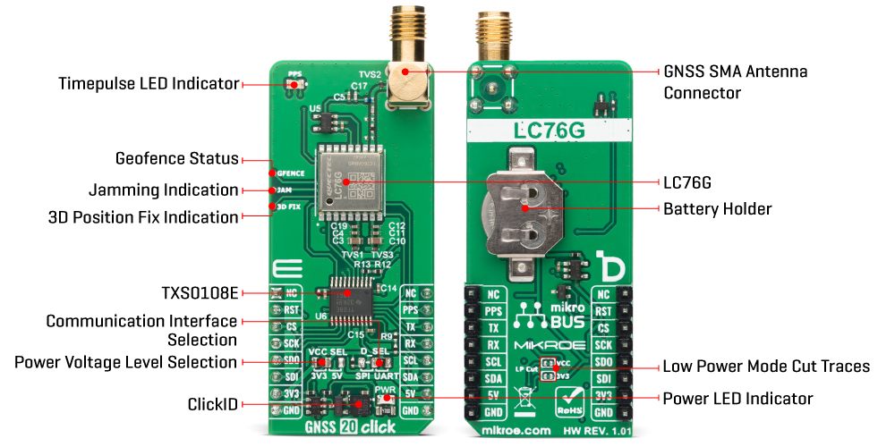
The GNSS 20 Click allows flexible communication with a host MCU through UART, SPI, or I2C interfaces. Both the UART and SPI interfaces can be used not only for standard communication but also for performing firmware upgrades when the module operates in Download mode, providing additional versatility and simplified maintenance. The I2C interface, on the other hand, is dedicated exclusively to communication, offering a straightforward way to exchange data with the host MCU. To switch between UART and SPI operation, the board features a D_SEL jumper that enables users to select the desired interface by placing the jumper in the appropriate position.
Along with the communication and control pins, this Click board™ also includes a reset pin (RST) enabling easy module resetting and an orange PPS LED indicator, which, in combination with the PPS pin, detects a synchronized pulse signal from the LC76G (AB) once per second. The board is also equipped with three dedicated test points that provide access to additional status signals from the integrated module, offering users enhanced monitoring and diagnostic capabilities.
The GFENCE signal indicates the current geofence status, allowing the system to detect when the tracked device enters or leaves predefined geographic boundaries. The JAM signal provides information in the event of signal jamming, enabling timely detection of interference and improving system reliability in environments with potential GNSS disruptions. The 3D FIX signal indicates a successful three-dimensional position fix, confirming that the module has achieved accurate positioning across latitude, longitude, and altitude. The board also features one SMA connector for GNSS antenna that MIKROE offers, like the Active GPS Antenna for flexible connectivity options.
In addition to its primary power supply configuration, GNSS 20 Click supports standalone operation through a dedicated backup power circuit. A coin-cell battery mounted on the back side of the board allows the module to retain critical timing and satellite data even when the main power supply is removed. On the back side of the board, there are two LP (low power) traces that can be cut if additional energy savings are required during operation of this Click board. By disconnecting these traces, the module can further reduce its overall power consumption, making it especially useful in battery-powered or energy-sensitive applications where maximizing efficiency is crucial.
This Click board™ can operate with both 3.3V and 5V logic voltage levels selected via the VCC SEL jumper. Since the LC76G (AB) module operates at 3.3V, logic-level translator, the TXS0108E, is also used for proper operation and an accurate signal-level translation. This way, both 3.3V and 5V capable MCUs can use the communication lines properly. Also, this Click board™ comes equipped with a library containing easy-to-use functions and an example code that can be used as a reference for further development.
Type
GPS/GNSS
Applications
Ideal for toll tags, emergency beacons, and battery-powered tracking applications such as containers, pallets, or animal monitoring
On-board modules
LC76G (AB) - GNSS module from Quectel
Key Features
Concurrent reception of GPS, GLONASS, Galileo, BDS and QZSS constellations, high sensitivity with integrated LNA, reduced time-to-first-fix and improved positioning accuracy, EASY embedded assist system with up to three days of predicted orbit data, ALP* low-power adaptive mode, UART, SPI or I2C interfaces, firmware upgrade support, geofence, jamming detection and 3D position fix status, and more
Interface
I2C,SPI,UART
Feature
ClickID
Compatibility
mikroBUS™
Click board size
L (57.15 x 25.4 mm)
Input Voltage
3.3V or 5V
This table shows how the pinout on GNSS 20 Click corresponds to the pinout on the mikroBUS™ socket (the latter shown in the two middle columns).
| Notes | Pin | Pin | Notes | ||||
|---|---|---|---|---|---|---|---|
| NC | 1 | AN | PWM | 16 | NC | ||
| Reset / ID SEL | RST | 2 | RST | INT | 15 | PPS | Timepulse Signal |
| SPI Select / ID COMM | CS | 3 | CS | RX | 14 | TX | UART TX |
| SPI Clock | SCK | 4 | SCK | TX | 13 | RX | UART RX |
| SPI Data OUT | SDO | 5 | MISO | SCL | 12 | SCL | I2C Clock |
| SPI Data IN | SDI | 6 | MOSI | SDA | 11 | SDA | I2C Data |
| Power Supply | 3.3V | 7 | 3.3V | 5V | 10 | 5V | Power Supply |
| Ground | GND | 8 | GND | GND | 9 | GND | Ground |
| Label | Name | Default | Description |
|---|---|---|---|
| LD1 | PWR | - | Power LED Indicator |
| LD2 | PPS | - | Timepulse LED Indicator |
| JP1 | VCC SEL | Left | Power Voltage Level Selection 3V3/5V: Left position 3V3, Right position 5V |
| JP2 | D_SEL | Right | Communication Interface Selection SPI/UART: Left position SPI, Right position UART |
| NT1-NT2 | LP CUT | Connected | Low Power Mode Cut Traces |
| Description | Min | Typ | Max | Unit |
|---|---|---|---|---|
| Supply Voltage | 3.3 | - | 5 | V |
| Frequency Range | 1559 | - | 1606 | MHz |
| Sensitivity (Tracking) | - | -166 | - | dBm |
| Sensitivity (Acquisition) | - | -147 | - | dBm |
| EASY TTFF (Cold Start) | - | 15 | - | sec |
GNSS 20 Click demo application is developed using the NECTO Studio, ensuring compatibility with mikroSDK's open-source libraries and tools. Designed for plug-and-play implementation and testing, the demo is fully compatible with all development, starter, and mikromedia boards featuring a mikroBUS™ socket.
Example Description
This example demonstrates the use of GNSS 20 Click by reading and displaying the GNSS coordinates.
Key Functions
gnss20_cfg_setup This function initializes Click configuration structure to initial values.gnss20_init This function initializes all necessary pins and peripherals used for this Click board.gnss20_generic_read This function reads a desired number of data bytes by using the selected serial interface.gnss20_parse_gga This function parses the GGA data from the read response buffer.gnss20_get_pps_pin This function returns the pulse per second (PPS) pin logic state.Application Init
Initializes the driver and logger.
Application Task
Reads the received data, parses the NMEA GGA info from it, and once it receives the position fix it will start displaying the coordinates on the USB UART.
Application Output
This Click board can be interfaced and monitored in two ways:
Additional Notes and Information
The complete application code and a ready-to-use project are available through the NECTO Studio Package Manager for direct installation in the NECTO Studio. The application code can also be found on the MIKROE GitHub account.
NOTE: Please be advised that any peripheral devices or accessories shown connected to the Click board™ are not included in the package. Check their availability in our shop or in the YMAN section below.

$9.50

$66.50

$533.40

$329.40

$239.20

$29.00

$23.20

$5.27

$2.88

$95.20

$314.30

$244.30

$244.30

$191.95

$209.30

$215.20

$199.20

$167.20
