


OFF
GO LOCAL
| Company | Stock | Price |
|---|---|---|


MIKROE-6641
17 g
Status:
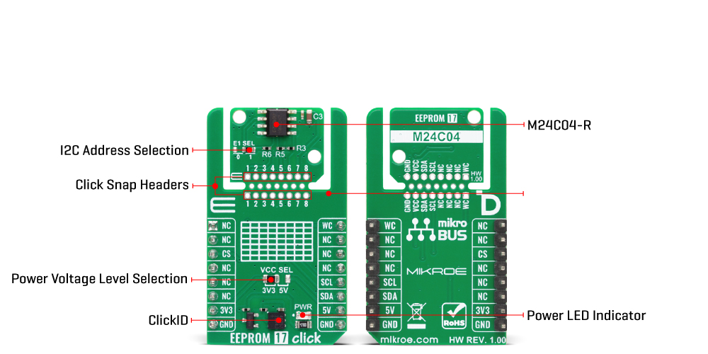
EEPROM 17 Click is a compact add-on board designed for reliable non-volatile data storage, ideal for preserving critical information such as system configurations, logs, and calibration data in embedded applications. This board features the M24C04-R, a 4Kbit serial I2C EEPROM from STMicroelectronics. The EEPROM features a 512-byte memory array with a 16-byte page size, supports random and sequential read modes, and enables byte and page writes in under 5ms. It includes a hardware write protection pin (WC), configurable I2C address via onboard jumper, and supports communication speeds up to 400kHz. A unique "Click Snap" design allows detaching the EEPROM section for flexible placement, with accessible IC pins and a fixed mounting hole for standalone use. EEPROM 17 Click is ideal for applications requiring long-term data retention and high write endurance, such as industrial controllers, IoT devices, or automotive systems.
EEPROM 17 Click is fully compatible with the mikroBUS™ socket and can be used on any host system supporting the mikroBUS™ standard. It comes with the mikroSDK open-source libraries, offering unparalleled flexibility for evaluation and customization. What sets this Click board™ apart is the groundbreaking ClickID feature, enabling your host system to automatically detect and identify this add-on board, alongside a Click Snap feature introducing a new level of flexibility and ease of use.
This product is no longer in stock
Availability date:
OFF
| Company | Stock | Price |
|---|---|---|
EEPROM 17 Click is based on the M24C04-R, a 4Kbit serial I2C bus EEPROM from STMicroelectronics, organized as 512 bytes with a page size of 16 bytes. This board provides a reliable and flexible non-volatile data storage solution ideally suited for a wide range of embedded applications. It supports both random and sequential read operations, enabling efficient data access patterns for various use cases, from simple data logging to configuration storage. The write functionality includes byte and page write modes, both capable of completing a write cycle in under 5 milliseconds, which ensures fast memory updates while maintaining system responsiveness.
The entire memory array can be write-protected to safeguard critical data against unintended modifications. The M24C04-R offers exceptional endurance with more than 4 million guaranteed write cycles per memory cell and ensures long-term data integrity with a data retention period exceeding 200 years.
This Click board™ is designed in a unique format supporting the newly introduced MIKROE feature called "Click Snap." Unlike the standardized version of Click boards, this feature allows the main sensor/IC/module area to become movable by breaking the PCB, opening up many new possibilities for implementation. Thanks to the Snap feature, the M24C04-R can operate autonomously by accessing its signals directly on the pins marked 1-8. Additionally, the Snap part includes a specified and fixed screw hole position, enabling users to secure the Snap board in their desired location.
This Click board™ uses an I2C interface with clock speeds of up to 400kHz, ensuring fast communication with the host MCU. The I2C address of the M24C04-R can be easily configured via onboard jumper marked E1 SEL in the Snap area, allowing multiple devices to coexist on the same bus. Beyond communication pins, this board is also equipped with a write control signal (WC) for protecting the entire contents of the memory from inadvertent write operations. Write operations are disabled to the entire memory array when write control (WC) is driven HIGH. When write control (WC) is driven HIGH, device select and address bytes are acknowledged; data bytes are not acknowledged.
This Click board™ can operate with either 3.3V or 5V logic voltage levels selected via the VCC SEL jumper. This way, both 3.3V and 5V capable MCUs can use the communication lines properly. Also, this Click board™ comes equipped with a library containing easy-to-use functions and an example code that can be used as a reference for further development.
Click Snap is an innovative feature of our standardized Click add-on boards, designed to bring greater flexibility and optimize your prototypes. By simply snapping the PCB along predefined lines, you can easily detach the main sensor/IC/module area, reducing the overall size, weight, and power consumption - ideal for the final phase of prototyping. For more details about Click Snap, visit the official page dedicated to this feature.
Type
EEPROM
Applications
Ideal for applications requiring long-term data retention and high write endurance, such as industrial controllers, IoT devices, or automotive systems
On-board modules
M24C04-R - 4Kbit serial I2C EEPROM from STMicroelectronics
Key Features
4Kbit EEPROM memory organized as 512 bytes, 16-byte page size, support for both random and sequential read modes, byte and page write operations completed in under 5 milliseconds, over 4 million write cycles per cell, more than 200 years of data retention, hardware write protection, I2C interface, Click Snap feature, and more
Interface
I2C
Feature
Click Snap,ClickID
Compatibility
mikroBUS™
Click board size
M (42.9 x 25.4 mm)
Input Voltage
3.3V or 5V
This table shows how the pinout on EEPROM 17 Click corresponds to the pinout on the mikroBUS™ socket (the latter shown in the two middle columns).
| Notes | Pin | Pin | Notes | ||||
|---|---|---|---|---|---|---|---|
| NC | 1 | AN | PWM | 16 | WC | Write Control | |
| NC | 2 | RST | INT | 15 | NC | ||
| ID COMM | CS | 3 | CS | RX | 14 | NC | |
| NC | 4 | SCK | TX | 13 | NC | ||
| NC | 5 | MISO | SCL | 12 | SCL | I2C Clock | |
| NC | 6 | MOSI | SDA | 11 | SDA | I2C Data | |
| Power Supply | 3.3V | 7 | 3.3V | 5V | 10 | 5V | Power Supply |
| Ground | GND | 8 | GND | GND | 9 | GND | Ground |
| Label | Name | Default | Description |
|---|---|---|---|
| LD1 | PWR | - | Power LED Indicator |
| JP1 | VCC SEL | Left | Power Voltage Level Selection 3V3/5V: Left position 3V3, Right position 5V |
| JP2 | E1 SEL | Right | I2C Address Selection 0/1: Left position 0, Right position 1 |
| Description | Min | Typ | Max | Unit |
|---|---|---|---|---|
| Supply Voltage | 3.3 | - | 5 | V |
| Memory Size | - | - | 4 | Kbit |
| Page Size | - | - | 16 | bytes |
| Data Retention | 200 | - | - | years |
| Write Endurance | 4M | - | - | cycles |
EEPROM 17 Click demo application is developed using the NECTO Studio, ensuring compatibility with mikroSDK's open-source libraries and tools. Designed for plug-and-play implementation and testing, the demo is fully compatible with all development, starter, and mikromedia boards featuring a mikroBUS™ socket.
Example Description
This example demonstrates the use of EEPROM 17 Click board by writing specified data to the memory and reading it back.
Key Functions
eeprom17_cfg_setup This function initializes Click configuration structure to initial values.eeprom17_init This function initializes all necessary pins and peripherals used for this Click board.eeprom17_write_memory This function writes data to the EEPROM memory starting from the specified address.eeprom17_read_memory This function reads data from the EEPROM memory starting from the specified address.eeprom17_select_bank This function selects the active memory bank in the EEPROM.Application Init
Initializes the driver and logger.
Application Task
Writes a desired number of bytes to the memory and then verifies if it is written correctly by reading from the same memory location and displaying the memory content on the USB UART.
Application Output
This Click board can be interfaced and monitored in two ways:
Additional Notes and Information
The complete application code and a ready-to-use project are available through the NECTO Studio Package Manager for direct installation in the NECTO Studio. The application code can also be found on the MIKROE GitHub account.
NOTE: Please be advised that any peripheral devices or accessories shown connected to the Click board™ are not included in the package. Check their availability in our shop or in the YMAN section below.

$1.20

$1.74

$3.00

$1.20

$889.00

$95.00

$549.00

$299.00

$29.00

$29.00

$6.59

$3.60

$119.00

$349.00

$349.00

$299.00

$449.00

$349.00

$269.00

$249.00

$209.00
