


OFF
GO LOCAL
| Company | Stock | Price |
|---|---|---|


MIKROE-6613
21 g
Status:
Stepper 27 Click is a compact add-on board designed for control of 2-phase stepper motors, enabling smooth, quiet, and high-resolution motion in embedded applications. It is based on the MAX22210, a highly integrated stepper motor driver from Analog Devices featuring two low-impedance H-bridges and a 128-microstep indexer. It includes non-dissipative integrated current sensing (ICS), supports selectable decay modes (slow, mixed, adaptive), and allows fine-tuned current control with an optional half full-scale setting for increased accuracy at lower currents. It features an advanced STEP/DIR control interface, fault protection functions (UVLO, OCP, TSD), sleep mode, and diagnostic TRIG outputs for external monitoring. Stepper 27 Click is ideal for applications requiring precise motion control, such as robotics, CNC machines, 3D printers, and industrial automation.
Stepper 27 Click is fully compatible with the mikroBUS™ socket and can be used on any host system supporting the mikroBUS™ standard. It comes with the mikroSDK open-source libraries, offering unparalleled flexibility for evaluation and customization. What sets this Click board™ apart is the groundbreaking ClickID feature, enabling your host system to automatically detect and identify this add-on board.
This product is no longer in stock
Availability date:
OFF
| Company | Stock | Price |
|---|---|---|
Stepper 27 Click is based on the MAX22210, a 2-phase stepper motor driver from Analog Devices. This highly integrated driver includes two low-impedance H-bridges with a typical total RON of just 0.25Ω (high side + low side), resulting in minimal power dissipation and efficient motor operation. The device incorporates an accurate current regulation system combined with a 128-microstep indexer that is controlled via a standard STEP/DIR interface, using the STP and DIR pins on the mikroBUS™ socket, and further configurable through MODE SEL jumpers. This advanced control logic enables smooth, quiet motor motion and makes it an ideal choice for precision motion applications.
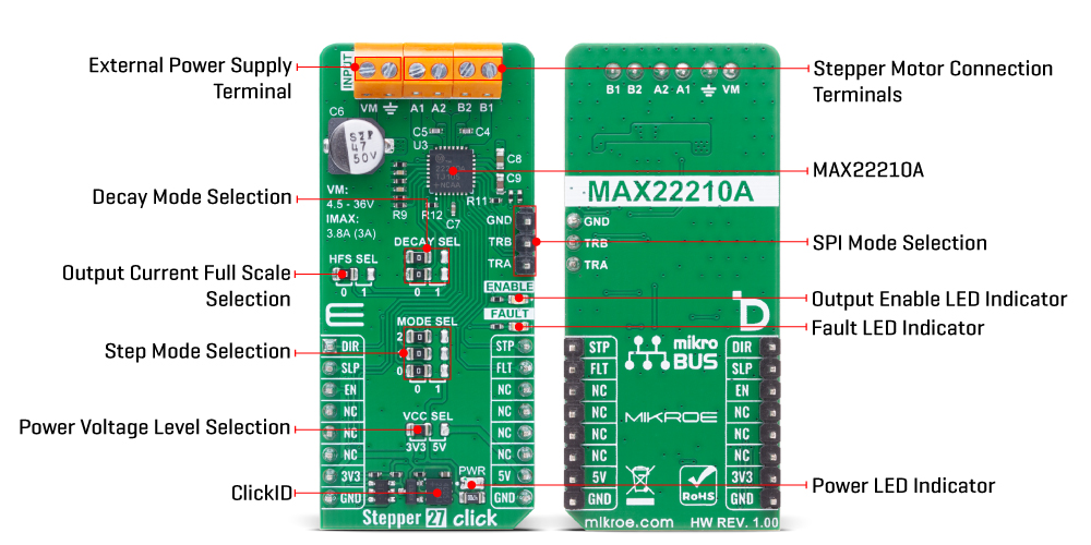
The current through the motor is monitored using non-dissipative Integrated Current Sensing (ICS) on the low-side FETs, which is compared to a programmed threshold. Once the current exceeds this threshold, the MAX22210 activates a decay phase using one of three selectable decay modes: slow, mixed, or adaptive. These decay modes are user-configurable through DECAY SEL jumpers, offering flexibility depending on the motor and load behavior. The board is powered from an external power supply via the VM terminal and supports a wide input voltage range from 4.5V to 36V. It delivers up to 3.8A of impulsive current for small capacitive loads, or up to 3A full-scale regulated current with built-in overcurrent protection to safeguard the driver and motor.
For use cases requiring high precision at lower currents - typically under 1.5A - the HFS SEL jumper can be configured to halve the full-scale current limit, doubling the low-side FET resistance and thus improving current control accuracy at the lower end of the range. Stepper 27 Click also includes robust fault protection features, such as thermal shutdown (TSD), undervoltage lockout (UVLO), and overcurrent protection.
The SLP pin enables low-power Sleep mode by shutting down all internal biasing and outputs, while the EN pin controls the activation of the motor outputs. Fault detection is handled via the FLT pin, which is open-drain and active-low, and is triggered in response to thermal, undervoltage, or overcurrent conditions. Visual feedback is provided by two onboard LEDs: a red FAULT LED and a yellow ENABLE LED, corresponding to FLT and EN pins respectively.
Additionally, the MAX22210 provides two open-drain TRIGA and TRIGB output signals, which can be used to trigger external ADCs for synchronized current measurements. These TRIGx signals reflect the internal PWM activity and can be used for real-time diagnostics such as detecting motor stalls or abnormal stepper behavior, offering valuable insight into the driver’s performance during operation.
This Click board™ can operate with either 3.3V or 5V logic voltage levels selected via the VCC SEL jumper. This way, both 3.3V and 5V capable MCUs can use the communication lines properly. Also, this Click board™ comes equipped with a library containing easy-to-use functions and an example code that can be used as a reference for further development.
Type
Stepper
Applications
Ideal for applications requiring precise motion control, such as robotics, CNC machines, 3D printers, and industrial automation
On-board modules
MAX22210 - 2-phase stepper motor driver from Analog Devices
Key Features
Two-phase stepper motor driver, dual low-impedance 0.25Ω H-bridges, integrated 128-microstep indexer, non-dissipative integrated current sensing, selectable decay modes, broad supply range with 3A full-scale and 3.8A peak current, optional half full-scale mode, protection features, and more
Interface
GPIO
Feature
ClickID
Compatibility
mikroBUS™
Click board size
L (57.15 x 25.4 mm)
Input Voltage
3.3V or 5V,External
This table shows how the pinout on Stepper 27 Click corresponds to the pinout on the mikroBUS™ socket (the latter shown in the two middle columns).
| Notes | Pin | Pin | Notes | ||||
|---|---|---|---|---|---|---|---|
| Direction Control | DIR | 1 | AN | PWM | 16 | STP | Step Control |
| Sleep Mode / ID SEL | SLP | 2 | RST | INT | 15 | FLT | Fault Indication |
| Output Enable / ID COMM | EN | 3 | CS | RX | 14 | NC | |
| NC | 4 | SCK | TX | 13 | NC | ||
| NC | 5 | MISO | SCL | 12 | NC | ||
| NC | 6 | MOSI | SDA | 11 | NC | ||
| Power Supply | 3.3V | 7 | 3.3V | 5V | 10 | 5V | Power Supply |
| Ground | GND | 8 | GND | GND | 9 | GND | Ground |
| Label | Name | Default | Description |
|---|---|---|---|
| LD1 | PWR | - | Power LED Indicator |
| LD2 | FAULT | - | Fault LED Indicator |
| LD3 | ENABLE | - | Output Enable LED Indicator |
| JP1 | VCC SEL | Left | Power Voltage Level Selection 3V3/5V: Left position 3V3, Right position 5V |
| JP2/JP4/JP6 | MODE SEL | Left | Step Mode Selection 0/1: Left position 0, Right position 1 |
| JP5/JP7 | DECAY SEL | Left | Decay Mode Selection 0/1: Left position 0, Right position 1 |
| JP3 | HFS SEL | Left | Output Current Full Scale Selection 0/1: Left position 0, Right position 1 |
| Description | Min | Typ | Max | Unit |
|---|---|---|---|---|
| Supply Voltage | 3.3 | - | 5 | V |
| External Power Supply Voltage | 4.5 | - | 36 | V |
| Peak Output Current | - | - | 3.8 | A |
| Full-Scale Output Current | - | - | 3 | A |
| Total H-bridge ON-resistance | - | 0.25 | - | Ω |
| Microstep Resolution | - | - | 128 | μsteps |
Stepper 27 Click demo application is developed using the NECTO Studio, ensuring compatibility with mikroSDK's open-source libraries and tools. Designed for plug-and-play implementation and testing, the demo is fully compatible with all development, starter, and mikromedia boards featuring a mikroBUS™ socket.
Example Description
This example demonstrates the use of the Stepper 27 Click board by driving the motor in both directions for a desired number of steps.
Key Functions
stepper27_cfg_setup This function initializes Click configuration structure to initial values.stepper27_init This function initializes all necessary pins and peripherals used for this Click board.stepper27_set_direction This function sets the motor direction by setting the DIR pin logic state.stepper27_drive_motor This function drives the motor for the specific number of steps at the selected speed.Application Init
Initializes the driver and resets the device.
Application Task
Drives the motor clockwise for 100 slow steps and 300 medium speed steps and then counter-clockwise for 400 fast steps with a 1 second delay on driving mode change. All data is being logged on the USB UART where you can track the program flow.
Application Output
This Click board can be interfaced and monitored in two ways:
Additional Notes and Information
The complete application code and a ready-to-use project are available through the NECTO Studio Package Manager for direct installation in the NECTO Studio. The application code can also be found on the MIKROE GitHub account.
NOTE: Please be advised that any peripheral devices or accessories shown connected to the Click board™ are not included in the package. Check their availability in our shop or in the YMAN section below.

$889.00

$95.00

$549.00

$299.00

$29.00

$29.00

$6.59

$3.60

$119.00

$349.00

$349.00

$299.00

$449.00

$349.00

$269.00

$249.00

$209.00
