


OFF
GO LOCAL
| Company | Stock | Price |
|---|---|---|


MIKROE-6610
20 g
Status:
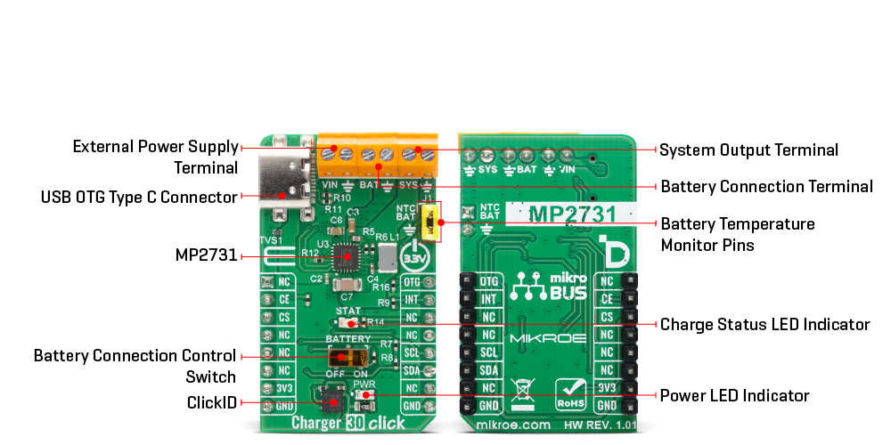
Charger 30 Click is a compact add-on board that provides a single-cell Li-ion or Li-polymer battery charging and system power management solution for embedded applications, enabling users to quickly integrate reliable charging and power-path control into their systems. It is based on the MP2731, a 4.5A switch-mode battery charge management device from Monolithic Power Systems (MPS). This board combines synchronous switching with NVDC system power path management to lower impedance, shorten charging time, and extend battery life, while offering an input voltage range of 3.7V to 16V at the VIN terminal and up to 4.5A output through the SYS terminal. Communication and control are achieved via an I2C interface, allowing configuration of charging parameters, system settings, and USB On-The-Go (OTG) operation, supported by a charge enable and a BATTERY switch for safe isolation or system resets. This makes Charger 30 Click ideal for portable applications such as smartphones, tablets, wireless cameras, and other battery-powered embedded devices.
Charger 30 Click is fully compatible with the mikroBUS™ socket and can be used on any host system supporting the mikroBUS™ standard. It comes with the mikroSDK open-source libraries, offering unparalleled flexibility for evaluation and customization. What sets this Click board™ apart is the groundbreaking ClickID feature, enabling your host system to automatically detect and identify this add-on board.
This product is no longer in stock
Availability date:
OFF
| Company | Stock | Price |
|---|---|---|
Charger 30 Click is based on the MP2731, a 4.5A switch-mode battery charge management device from Monolithic Power Systems (MPS). It provides a single-cell Li-ion or Li-polymer battery charging and system power management solution. This IC combines synchronous switching with NVDC system power path management to reduce impedance, shorten charging times, and extend battery lifespan, making it ideal for portable applications such as smartphones, tablets, wireless cameras, and other battery-powered embedded devices. The board accepts an input voltage from 3.7V to 16V through its VIN terminal and delivers up to 4.5A to the system load via the SYS terminal, ensuring stable power delivery under demanding conditions.
Communication and control are handled through an I2C serial interface, which allows flexible configuration of charging parameters, system settings, and OTG operation. Battery charging is enabled or disabled by software and by forcing the CE pin to a LOW logic level, which can also be used to restart a new charging cycle. The MP2731 automatically detects the battery voltage and executes a multi-stage charging profile, terminating the charge when full capacity is reached and automatically initiating a new cycle if the battery voltage drops below the recharge threshold.
Charger 30 Click also incorporates a dedicated BATTERY switch to disconnect the battery from the system power path, enabling a system power reset or safe battery isolation without unplugging the cell. A red STAT LED connected to the open-drain status output indicates charger operation modes by lighting steadily during active charging, turning off when charging is complete, or blinking when charging is suspended. The board integrates a standard USB host connector with fast charge capabilities and supports USB On-The-Go (OTG) operation by supplying a default 5V boost output for powering external peripherals.
The OTG function is enabled through I2C control, and the OTG pin on the Click can be pulled LOW to suspend boost operation during OTG mode. Many safety and protection features ensure reliable and secure operation, including a programmable charging safety timer, battery temperature monitoring via dedicated NTC header pins, and built-in overvoltage and overcurrent protections. In the event of a fault condition, the device asserts an INT interrupt signal to the host MCU to allow immediate response and system protection.
This Click board™ can be operated only with a 3.3V logic voltage level. The board must perform appropriate logic voltage level conversion before using MCUs with different logic levels. It also comes equipped with a library containing functions and example code that can be used as a reference for further development.
Type
Battery charger
Applications
Ideal for portable applications such as smartphones, tablets, wireless cameras, and other battery-powered embedded devices
On-board modules
MP2731 - 4.5A switch-mode battery charge management device from MPS
Key Features
Single-cell Li-ion or Li-polymer battery charging and system power management solution, synchronous switching with NVDC system power path management, I2C serial interface for configuration of charging parameters, system settings and OTG operation, automatic battery voltage detection with multi-stage charging profile and automatic recharge, BATTERY switch for battery isolation or system reset, and more
Interface
I2C
Feature
ClickID
Compatibility
mikroBUS™
Click board size
M (42.9 x 25.4 mm)
Input Voltage
3.3V,External
This table shows how the pinout on Charger 30 Click corresponds to the pinout on the mikroBUS™ socket (the latter shown in the two middle columns).
| Notes | Pin | Pin | Notes | ||||
|---|---|---|---|---|---|---|---|
| NC | 1 | AN | PWM | 16 | OTG | OTG Boost Suspend | |
| Charging Control | CE | 2 | RST | INT | 15 | INT | Interrupt |
| ID COMM | CS | 3 | CS | RX | 14 | NC | |
| NC | 4 | SCK | TX | 13 | NC | ||
| NC | 5 | MISO | SCL | 12 | SCL | I2C Clock | |
| NC | 6 | MOSI | SDA | 11 | SDA | I2C Data | |
| Power Supply | 3.3V | 7 | 3.3V | 5V | 10 | NC | |
| Ground | GND | 8 | GND | GND | 9 | GND | Ground |
| Label | Name | Default | Description |
|---|---|---|---|
| LD1 | PWR | - | Power LED Indicator |
| LD2 | STAT | - | Charge Status LED Indicator |
| SW1 | BATTERY | Right | Battery Connection Control Switch OFF/ON: Left position OFF, Right position ON |
| Description | Min | Typ | Max | Unit |
|---|---|---|---|---|
| Supply Voltage | - | 3.3 | - | V |
| External Power Supply (VIN) | 3.7 | - | 16 | V |
| System Output Current | - | - | 4.5 | A |
Charger 30 Click demo application is developed using the NECTO Studio, ensuring compatibility with mikroSDK's open-source libraries and tools. Designed for plug-and-play implementation and testing, the demo is fully compatible with all development, starter, and mikromedia boards featuring a mikroBUS™ socket.
Example Description
This example demonstrates the use of the Charger 30 Click board by reading and logging the charging status, input and battery voltage, current consumption, and fault diagnostics. The demo configures the default setup and then periodically polls for system status and fault information.
Key Functions
charger30_cfg_setup This function initializes Click configuration structure to initial values.charger30_init This function initializes all necessary pins and peripherals used for this Click board.charger30_default_cfg This function executes a default configuration of Charger 30 Click board.charger30_read_status This function reads multiple status and monitoring registers and stores the values into the provided status structure.Application Init
Initializes the logger and the Charger 30 Click driver and applies the default configuration.
Application Task
Periodically reads and logs charger status and fault registers along with voltage, current.
Application Output
This Click board can be interfaced and monitored in two ways:
Additional Notes and Information
The complete application code and a ready-to-use project are available through the NECTO Studio Package Manager for direct installation in the NECTO Studio. The application code can also be found on the MIKROE GitHub account.
NOTE: Please be advised that any peripheral devices or accessories shown connected to the Click board™ are not included in the package. Check their availability in our shop or in the YMAN section below.

$15.00

$889.00

$95.00

$549.00

$299.00

$29.00

$29.00

$6.59

$3.60

$119.00

$449.00

$349.00

$349.00

$349.00

$299.00

$269.00

$249.00

$209.00
