


OFF
GO LOCAL
| Company | Stock | Price |
|---|---|---|


MIKROE-6576
16 g
Status:
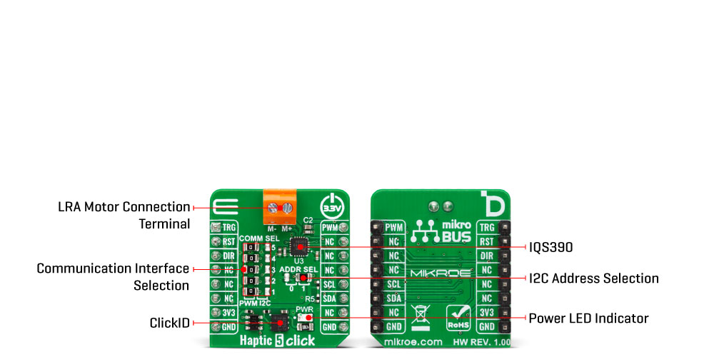
Haptic 5 Click is a compact add-on board designed to provide high-performance haptic feedback using Linear Resonant Actuators (LRA), making it ideal for creating precise and responsive tactile effects in embedded applications. It is based on the IQS390 haptic driver IC from Azoteq, which features both I2C and PWM control modes. The IQS390 supports real-time closed-loop auto-resonance tracking in I2C mode, automatic power management with ultra-low power operation, and selectable drive frequency. Haptic 5 Click is best suited for applications such as touchpad feedback, mouse wheel scrolling, membrane keypads, and haptic notifications in consumer or industrial devices.
Haptic 5 Click is fully compatible with the mikroBUS™ socket and can be used on any host system supporting the mikroBUS™ standard. It comes with the mikroSDK open-source libraries, offering unparalleled flexibility for evaluation and customization. What sets this Click board™ apart is the groundbreaking ClickID feature, enabling your host system to automatically detect and identify this add-on board.
This product is no longer in stock
Availability date:
OFF
| Company | Stock | Price |
|---|---|---|
Haptic 5 Click is based on the IQS390 haptic driver IC from Azoteq, designed to provide high-performance haptic feedback using Linear Resonant Actuators (LRA). This board supports two operating modes— I2C and PWM— selectable via the COMM SEL jumpers. To ensure proper operation, all jumpers must be aligned to the same mode side. In I2C mode, the IQS390 employs a real-time closed-loop auto-resonance algorithm that dynamically tracks and matches the resonant frequency of the connected LRA motor, ensuring efficient and consistent vibration output. Haptic 5 Click is ideal for applications that require precise and responsive tactile feedback, such as mouse wheel scrolling effects, trackpad interactions, doorbell notifications, and membrane keypads.
The I2C interface supports communication speeds of up to Fast Mode Plus (1 MHz), with a selectable I2C address configured via the ADDR SEL jumper, enabling flexible integration into various systems. Additionally, the IQS390 includes a dedicated RST pin for hardware reset, and haptic pulses can be triggered either through I2C commands or externally via the TRG pin. In PWM mode, the board accepts an external Pulse Width Modulated signal along with a motor drive direction input via the DIR pin. Both operating modes feature automatic power mode management, including an ultra-low power state to reduce energy consumption during inactivity.
This Click board™ can be operated only with a 3.3V logic voltage level. The board must perform appropriate logic voltage level conversion before using MCUs with different logic levels. It also comes equipped with a library containing functions and example code that can be used as a reference for further development.
Type
Haptic
Applications
Ideal for touchpad feedback, mouse wheel scrolling, membrane keypads, and haptic notifications in consumer or industrial devices
On-board modules
IQS390 - LRA haptic driver from Azoteq
Key Features
Support for Linear Resonant Actuator (LRA) control, dual operating modes (I2C and PWM), real-time closed-loop auto-resonance algorithm in I2C mode, configurable I2C address, external trigger input, hardware reset, PWM input with motor direction control, automatic power mode management with ultra-low power operation, and more
Interface
I2C,PWM
Feature
ClickID
Compatibility
mikroBUS™
Click board size
S (28.6 x 25.4 mm)
Input Voltage
3.3V
This table shows how the pinout on Haptic 5 Click corresponds to the pinout on the mikroBUS™ socket (the latter shown in the two middle columns).
| Notes | Pin | Pin | Notes | ||||
|---|---|---|---|---|---|---|---|
| Haptic Pulse Trigger | TRG | 1 | AN | PWM | 16 | PWM | PWM Signal |
| Reset / ID SEL | RST | 2 | RST | INT | 15 | NC | |
| Direction Control / ID COMM | DIR | 3 | CS | RX | 14 | NC | |
| NC | 4 | SCK | TX | 13 | NC | ||
| NC | 5 | MISO | SCL | 12 | SCL | I2C Clock | |
| NC | 6 | MOSI | SDA | 11 | SDA | I2C Data | |
| Power Supply | 3.3V | 7 | 3.3V | 5V | 10 | NC | |
| Ground | GND | 8 | GND | GND | 9 | GND | Ground |
| Label | Name | Default | Description |
|---|---|---|---|
| LD1 | PWR | - | Power LED Indicator |
| JP1-JP5 | COMM SEL | Left | Communication Interface Selection PWM/I2C: Left position PWM, Right position I2C |
| JP6 | ADDR SEL | Right | I2C Address Selection 0/1: Left position 0, Right position 1 |
| Description | Min | Typ | Max | Unit |
|---|---|---|---|---|
| Supply Voltage | - | 3.3 | - | V |
| PWM Input Frequency | - | - | 300 | Hz |
Haptic 5 Click demo application is developed using the NECTO Studio, ensuring compatibility with mikroSDK's open-source libraries and tools. Designed for plug-and-play implementation and testing, the demo is fully compatible with all development, starter, and mikromedia boards featuring a mikroBUS™ socket.
Example Description
This example demonstrates the control of the Haptic 5 Click board. In I2C mode, the example toggles the haptic trigger pin periodically to generate vibration pulses. In PWM mode, it gradually increases and decreases the output duty cycle to modulate the vibration intensity, while toggling the direction when the duty reaches 0%.
Key Functions
haptic5_cfg_setup This function initializes Click configuration structure to initial values.haptic5_init This function initializes all necessary pins and peripherals used for this Click board.haptic5_default_cfg This function executes a default configuration of Haptic 5 Click board.haptic5_set_duty_cycle This function sets the PWM duty cycle.haptic5_toggle_dir This function toggles the state of the DIR pin.Application Init
Initializes the logger and the Click board driver, and applies the default configuration.
Application Task
Depending on the selected communication interface (I2C or PWM), toggles the haptic trigger (I2C), or changes PWM duty cycle and direction (PWM).
Application Output
This Click board can be interfaced and monitored in two ways:
Additional Notes and Information
The complete application code and a ready-to-use project are available through the NECTO Studio Package Manager for direct installation in the NECTO Studio. The application code can also be found on the MIKROE GitHub account.
NOTE: Please be advised that any peripheral devices or accessories shown connected to the Click board™ are not included in the package. Check their availability in our shop or in the YMAN section below.

$889.00

$95.00

$549.00

$299.00

$29.00

$29.00

$6.59

$3.60

$119.00

$349.00

$349.00

$299.00

$449.00

$349.00

$269.00

$249.00

$209.00
