


20%
OFF
GO LOCAL
| Company | Stock | Price |
|---|---|---|


MIKROE-6533
22 g
Status:
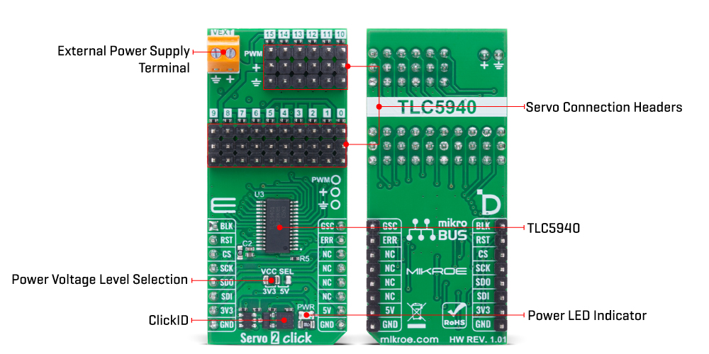
Servo 2 Click is a compact add-on board designed for precise control of multiple standard servo motors. It is based on the TLC59401, a 16-channel constant-current sink LED driver from Texas Instruments with integrated PWM control. Each channel supports 12-bit resolution for fine-grained pulse width modulation, with up to 4096 steps of adjustment, and can deliver up to 120mA of current, defined by an external resistor. Communication is achieved via a high-speed 4-wire SPI interface, and the board supports both 3.3V and 5V logic levels. The connected load is powered through a single VEXT terminal supporting up to 17V, while additional safety features include open-load detection and thermal error flags. This Click board™ is ideal for applications such as robotics, motorized actuators, and automation systems, while also supporting secondary use in LED display control.
Servo 2 Click is fully compatible with the mikroBUS™ socket and can be used on any host system supporting the mikroBUS™ standard. It comes with the mikroSDK open-source libraries, offering unparalleled flexibility for evaluation and customization. What sets this Click board™ apart is the groundbreaking ClickID feature, enabling your host system to seamlessly and automatically detect and identify this add-on board.
This product is no longer in stock
Availability date:
20%
OFF
| Company | Stock | Price |
|---|---|---|
Servo 2 Click is based on the TLC59401, a 16-channel LED driver from Texas Instruments designed to control multiple outputs using a high-precision constant-current sink architecture. Each of the 16 channels features an individually programmable 12-bit grayscale PWM control, allowing for 4096 levels of pulse width adjustment per output. This level of control is accessible via a serial interface, ensuring flexible and accurate operation across all channels. The maximum output current for each channel is defined by a single external resistor, which simplifies configuration. On the Servo 2 Click, this resistor is set to 330Ω (R7), resulting in a maximum current of approximately 120mA per channel. This makes the board well-suited not only for precise servo motor control but also for driving high-current LEDs in secondary applications, including monocolor, multicolor, and full-color LED displays, signboards, and back-lighting systems where accurate brightness control and current regulation are essential.
This Click board™ establishes communication with the host MCU via a 4-wire SPI interface with a maximum clock frequency of 30MHz, ensuring reliable and high-speed data transfer. Beyond the SPI pins, the board includes additional control and status lines that enhance its functionality. The BLK pin is used to blank all outputs simultaneously - when set HIGH, all output channels are disabled and the internal grayscale counter is reset. When driven LOW, the outputs resume operation under the control of the internal PWM grayscale engine. The design also supports the parallel configuration of multiple output channels to increase total current-driving capability.
The supply voltage for the connected loads is provided through the VEXT terminal, which distributes the same voltage to all output channels. This voltage can go up to a maximum of 17V, making the board compatible with a wide range of connected devices, including servo motors and LEDs. Additionally, the ERR pin provides essential fault indication through two integrated monitoring features: LED open detection (LOD), which flags disconnected or broken LEDs, and the thermal error flag (TEF), which signals an over-temperature condition.
This Click board™ can operate with either 3.3V or 5V logic voltage levels selected via the VCC SEL jumper. This way, both 3.3V and 5V capable MCUs can use the communication lines properly. Also, this Click board™ comes equipped with a library containing easy-to-use functions and an example code that can be used as a reference for further development.
Type
Servo
Applications
Ideal for applications such as robotics, motorized actuators, and automation systems, while also supporting secondary use in LED display control
On-board modules
TLC59401 - 16-channel constant-current sink LED driver from Texas Instruments
Key Features
12-bit PWM control, SPI interface up to 30MHz, individual channel current up to 120mA, external current setting resistor, VEXT supply up to 17V, parallel output configuration support, servo motor and LED control capability, BLK pin for output blanking, ERR pin for fault detection (LOD and TEF), and more
Interface
PWM,SPI
Feature
ClickID
Compatibility
mikroBUS™
Click board size
L (57.15 x 25.4 mm)
Input Voltage
3.3V or 5V,External
This table shows how the pinout on Servo 2 Click corresponds to the pinout on the mikroBUS™ socket (the latter shown in the two middle columns).
| Notes | Pin | Pin | Notes | ||||
|---|---|---|---|---|---|---|---|
| Output Channel Control | BLK | 1 | AN | PWM | 16 | GSC | Grayscale PWM control |
| ID SEL | RST | 2 | RST | INT | 15 | ERR | Error Detection |
| SPI Select / ID COMM | CS | 3 | CS | RX | 14 | NC | |
| SPI Clock | SCK | 4 | SCK | TX | 13 | NC | |
| SPI Data OUT | SDO | 5 | MISO | SCL | 12 | NC | |
| SPI Data IN | SDI | 6 | MOSI | SDA | 11 | NC | |
| Power Supply | 3.3V | 7 | 3.3V | 5V | 10 | 5V | Power Supply |
| Ground | GND | 8 | GND | GND | 9 | GND | Ground |
| Label | Name | Default | Description |
|---|---|---|---|
| LD1 | PWR | - | Power LED Indicator |
| JP1 | VCC SEL | Left | Power Voltage Level Selection 3V3/5V: Left position 3V3, Right position 5V |
| Description | Min | Typ | Max | Unit |
|---|---|---|---|---|
| Supply Voltage | 3.3 | - | 5 | V |
| External Power Supply | - | - | 17 | V |
| Output Current per Channel | - | - | 120 | mA |
| PWM Resolution | - | 12 | - | bit |
Servo 2 Click demo application is developed using the NECTO Studio, ensuring compatibility with mikroSDK's open-source libraries and tools. Designed for plug-and-play implementation and testing, the demo is fully compatible with all development, starter, and mikromedia boards featuring a mikroBUS™ socket.
Example Description
This example demonstrates the use of the Servo 2 Click board for controlling the angle of servo motors. The board is capable of driving multiple servos, and the example illustrates how to change the angle of all connected servos simultaneously within a defined range.
Key Functions
servo2_cfg_setup Config Object Initialization function.servo2_init Initialization function.servo2_set_angle This function sets the servo angle for a specific channel or all channels.servo2_update_output This function updates the PWM output values for all channels by writing them to the device.servo2_set_channel_pwm This function sets the PWM output for a specific channel or all channels.Application Init
Initializes the logger module and configures the Servo 2 Click board. The PWM communication is established, and the device is prepared for controlling the servos.
Application Task
Gradually changes the angle of all connected servo motors from a minimum to a maximum value, and then back to the minimum, creating a sweeping motion. The current angle is logged during each update.
Application Output
This Click board can be interfaced and monitored in two ways:
Additional Notes and Information
The complete application code and a ready-to-use project are available through the NECTO Studio Package Manager for direct installation in the NECTO Studio. The application code can also be found on the MIKROE GitHub account.
NOTE: Please be advised that any peripheral devices or accessories shown connected to the Click board™ are not included in the package. Check their availability in our shop or in the YMAN section below.

$533.40

$66.50

$329.40

$239.20

$29.00

$23.20

$5.27

$2.88

$95.20

$244.30

$244.30

$191.95

$209.30

$314.30

$215.20

$199.20

$167.20
