


OFF
GO LOCAL
| Company | Stock | Price |
|---|---|---|


MIKROE-5591
18 g
Status:
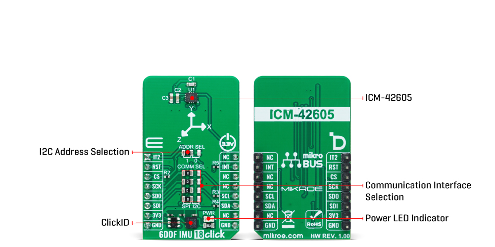
6DOF IMU 18 Click is a compact add-on board with a 6-axis inertial measurement unit. This board features the ICM-42605, a high-performance 6-axis MotionTracking™ IMU from TDK InvenSense. It combines a 3-axis gyroscope and a 3-axis accelerometer featuring a 2Kb-byte FIFO that can lower the traffic on the serial bus interface (SPI or I2C). It reduces power consumption by allowing the system processor to burst read sensor data and then go into a low-power mode. Thanks to the industry-leading feature, APEX Motion Processing engine, this Click board™ represents an excellent choice for applications like tilt sensing, navigation, orientation measurement, platform stabilization, robotics, and many more.
6DOF IMU 18 Click is fully compatible with the mikroBUS™ socket and can be used on any host system supporting the mikroBUS™ standard. It comes with the mikroSDK open-source libraries, offering unparalleled flexibility for evaluation and customization. What sets this Click board™ apart is the groundbreaking ClickID feature, enabling your host system to seamlessly and automatically detect and identify this add-on board.
This product is no longer in stock
Availability date:
OFF
| Company | Stock | Price |
|---|---|---|
6DOF IMU 18 Click is based on the ICM-42605, a 6-axis motion tracking device that combines a 3-axis gyroscope and a 3-axis accelerometer from TDK InvenSense. It features a 2K-byte FIFO that can lower the traffic on the selected serial bus interface and reduce power consumption by allowing the system processor to burst read sensor data and then go into a low-power mode. With its 6-axis integration, the ICM-42605 guarantees optimal motion performance for customers. The IICM-42605 supports an extended operating temperature range, allowing customers to design it into various industrial IoT applications, including navigation and stabilizing industrial machinery and robots.
The gyroscope supports eight programmable full-scale range settings from ±15.625dps to ±2000dps, and the accelerometer supports four programmable full-scale range settings from ±2g to ±16g. Other industry-leading features include on-chip 16-bit ADCs, programmable digital filters, an embedded temperature sensor, and programmable interrupts. The ICM-42605 also provides high robustness by supporting 20,000g shock reliability.
This Click board™ allows using both I2C and SPI interfaces at a maximum frequency of 1MHz for I2C and 24MHz for SPI communication. Selection is made by positioning SMD jumpers marked COMM SEL to the appropriate position. All jumpers must be on the same side, or the Click board™ may become unresponsive. When the I2C interface is selected, the ICM-42605 allows the choice of its I2C slave address, using the ADDR SEL SMD jumper set to an appropriate position marked 1 or 0. In addition to communication pins, this board also possesses additional interrupt pins, routed to the INT and IT2 pins on the mikroBUS™ socket, to signal MCU that an event, such as specific tap or sample acquisition conditions, has happened. Besides the standard interrupt function, the IT2 pin can also be used as a Frame Synchronization signal for synchronization with an external digital signal.
This Click board™ can only be operated with a 3.3V logic voltage level. The board must perform appropriate logic voltage level conversion before using MCUs with different logic levels. However, the Click board™ comes equipped with a library containing functions and an example code that can be used as a reference for further development.
Type
Motion
Applications
Can be used for applications like tilt sensing, navigation, orientation measurement, platform stabilization, robotics, and many more
On-board modules
ICM-42605 - 6-axis MotionTracking™ IMU from TDK InvenSense
Key Features
Low power consumption, digital-output X-, Y-, and Z-axis angular rate sensors with programmable full-scale range, user-programmable interrupts, 20.000g shock tolerant, and more
Interface
I2C,I3C,SPI
Feature
ClickID
Compatibility
mikroBUS™
Click board size
S (28.6 x 25.4 mm)
Input Voltage
3.3V
This table shows how the pinout on 6DOF IMU 18 Click corresponds to the pinout on the mikroBUS™ socket (the latter shown in the two middle columns).
| Notes | Pin | Pin | Notes | ||||
|---|---|---|---|---|---|---|---|
| Interrupt/Frame Sync | IT2 | 1 | AN | PWM | 16 | NC | |
| ID SEL | RST | 2 | RST | INT | 15 | INT | Interrupt |
| SPI Select / ID COMM | CS | 3 | CS | RX | 14 | NC | |
| SPI Clock | SCK | 4 | SCK | TX | 13 | NC | |
| SPI Data OUT | SDO | 5 | MISO | SCL | 12 | SCL | I2C Clock |
| SPI Data IN | SDI | 6 | MOSI | SDA | 11 | SDA | I2C Data |
| Power Supply | 3.3V | 7 | 3.3V | 5V | 10 | NC | |
| Ground | GND | 8 | GND | GND | 9 | GND | Ground |
| Label | Name | Default | Description |
|---|---|---|---|
| LD1 | PWR | - | Power LED Indicator |
| JP1-JP4 | COMM SEL | Left | Communication Interface Selection SPI/I2C: Left position SPI, Right position I2C |
| JP5 | ADDR SEL | Left | I2C Address Selection 0/1: Left position 0, Right position 1 |
| Description | Min | Typ | Max | Unit |
|---|---|---|---|---|
| Supply Voltage | - | 3.3 | - | V |
| Gyroscope Full-Scale Range | ±15.625 | - | ±2000 | dps |
| Accelerometer Full-Scale Range | ±2 | - | ±16 | g |
| Gyroscope Sensitivity | 16 | - | 2097.2 | LSB/dps |
| Accelerometer Sensitivity | 2.048 | - | 16.384 | LSB/g |
We provide a library for the 6DOF IMU 18 Click as well as a demo application (example), developed using Mikroe compilers. The demo can run on all the main Mikroe development boards.
Package can be downloaded/installed directly from NECTO Studio Package Manager (recommended), downloaded from our LibStock™ or found on Mikroe github account.
Library Description
This library contains API for 6DOF IMU 18 Click driver.
Key functions
c6dofimu18_set_reg_bank 6DOF IMU 18 set register bank function.
c6dofimu18_get_int1_state 6DOF IMU 18 read INT1 pin state function.
c6dofimu18_get_data_from_register 6DOF IMU 18 read data function.
Example Description
This library contains API for 6DOF IMU 18 Click driver. The library initializes and defines the I2C and SPI bus drivers to write and read data from registers, as well as the default
configuration for reading gyroscope and accelerator data, and temperature.
void application_task ( void )
 {
     if ( c6dofimu18_get_int1_state( &c6dofimu18) )
     {
         c6dofimu18_data_t accel_data;
         c6dofimu18_data_t gyro_data;
         float temp_data;
         uint32_t tmst_data;

         c6dofimu18_get_data_from_register( &c6dofimu18, &temp_data, &accel_data, &gyro_data, &tmst_data );
         log_printf( &logger, " TEMP: %.2f rn", temp_data );
         log_printf( &logger, " GYRO: x:%d y:%d z:%d rn", gyro_data.data_x,gyro_data.data_y,gyro_data.data_z );
         log_printf( &logger, " ACCEL: x:%d y:%d z:%d rn", accel_data.data_x,accel_data.data_y,accel_data.data_z );
         log_printf( &logger, "========================== rn" );
         Delay_ms( 1000 );
     }
 }
The full application code, and ready to use projects can be installed directly from NECTO Studio Package Manager (recommended), downloaded from our LibStock™ or found on Mikroe github account.
Other Mikroe Libraries used in the example:
Additional notes and informations
Depending on the development board you are using, you may need USB UART click, USB UART 2 Click or RS232 Click to connect to your PC, for development systems with no UART to USB interface available on the board. UART terminal is available in all Mikroe compilers.
This Click board™ is supported with mikroSDK - Mikroe Software Development Kit, which needs to be downloaded from the LibStock and installed for the compiler you are using to ensure proper operation of mikroSDK compliant Click board™ demo applications.
For more information about mikroSDK, visit the official page.
NOTE: Please be advised that any peripheral devices or accessories shown connected to the Click board™ are not included in the package. Check their availability in our shop or in the YMAN section below.

$889.00

$95.00

$549.00

$299.00

$29.00

$29.00

$6.59

$3.60

$119.00

$449.00

$349.00

$349.00

$349.00

$299.00

$269.00

$249.00

$209.00
