


OFF
GO LOCAL
| Company | Stock | Price |
|---|---|---|


MIKROE-5540
18 g
Status:
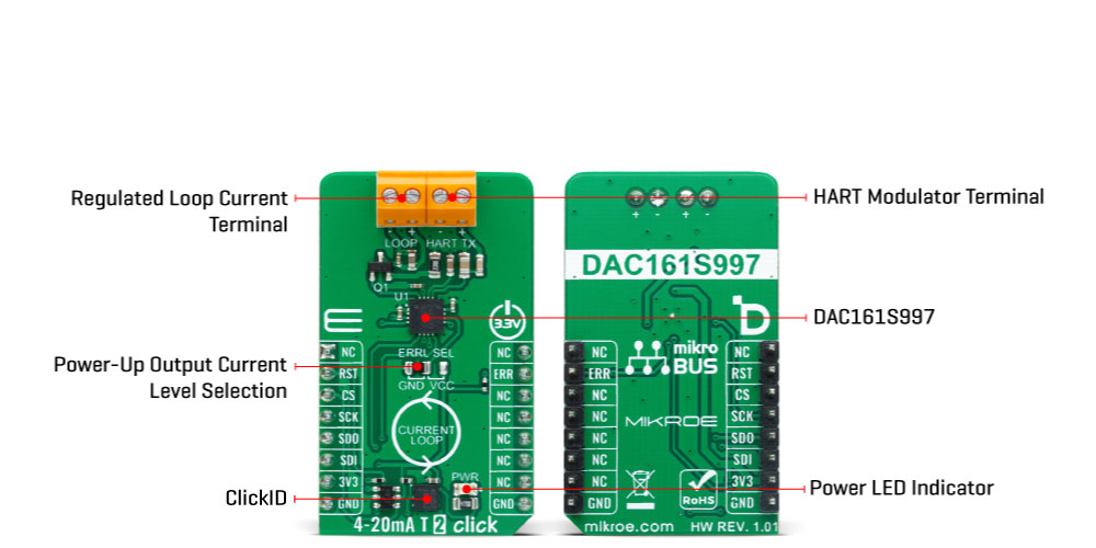
4-20mA T 2 Click is a compact add-on board for transmitting an analog output current over an industry-standard 4-20mA current loop. This board features DAC161S997, a low-power 16-bit ΣΔ digital-to-analog converter (DAC) from Texas Instruments. It has a programmable Power-Up condition and loop-error detection/reporting accessible via simple 4-wire SPI for data transfer and configuration of the DAC functions. In addition, it is characterized by low power consumption and the possibility of simple Highway Addressable Remote Transducer (HART) modulator interfacing, allowing the injection of FSK-modulated digital data into the 4-20mA current loop. This Click board™ is suitable for 2-wire 4-20mA current loop transmitters, industrial process control, low-power transmitters, and many more.
4-20mA T 2 Click is fully compatible with the mikroBUS™ socket and can be used on any host system supporting the mikroBUS™ standard. It comes with the mikroSDK open-source libraries, offering unparalleled flexibility for evaluation and customization. What sets this Click board™ apart is the groundbreaking ClickID feature, enabling your host system to seamlessly and automatically detect and identify this add-on board.
This product is no longer in stock
Availability date:
OFF
| Company | Stock | Price |
|---|---|---|
4-20mA T 2 Click is based on the DAC161S997, a low-power 16-bit ΣΔ digital-to-analog converter (DAC) from Texas Instruments, realized as a ΣΔ modulator. Next to ΣΔ DAC, the DAC161S997 also contains an internal ultra-low power voltage reference and an internal oscillator to reduce power and component count in compact loop-powered applications. This architecture, where DAC's output current represents a multiplied copy of the filtered modulator output, ensures an excellent linearity performance while minimizing the device's power consumption. In addition to an industry-standard 4-20 mA current loop over the LOOP terminal, the DAC161S997 also has the possibility of a simple Highway Addressable Remote Transducer (HART) modulator interfacing through an onboard HART TX terminal. It allows the injection of FSK-modulated digital data into the 4-20mA current loop.
This Click board™ communicates with MCU using a 4-wire SPI serial interface with a maximum frequency of 10MHz, for data transfer and configuration of the DAC functions. The DAC161S997 supports both Mode 0 and Mode 3 of the SPI protocol. 4-20mA T 2 Click comes with an additional feature, as an interrupt, available on the ERR pin of the mikroBUS™ socket, the loop-error detection/reporting feature. By default, the DAC161S997 detects and reports several types of errors, such as loop error, SPI timeout error (channel error), frame error, and alarm current.
In the case of a fault condition or during the initial Power-Up sequence, the DAC161S997 will output current in either the upper or lower error current band. The band's choice is user-selectable via the appropriate position of an onboard jumper ERRL SEL, while the current error value is programmable through the SPI interface.
This Click board™ can be operated only with a 3.3V logic voltage level. The board must perform appropriate logic voltage level conversion before using MCUs with different logic levels. However, the Click board™ comes equipped with a library containing functions and an example code that can be used as a reference for further development.
Type
Current
Applications
Can be used for 2-wire 4-20mA current loop transmitters, industrial process control, low-power transmitters, and more
On-board modules
DAC161S997 - 16-bit DAC for 4-20mA loops from Texas Instruments
Key Features
High resolution, industry-standard current loop, SPI-programmable, low power consumption, Power-Up programmable output current, loop-error detection and reporting, HART modulator interfacing, and more
Interface
SPI
Feature
ClickID
Compatibility
mikroBUS™
Click board size
M (42.9 x 25.4 mm)
Input Voltage
3.3V
This table shows how the pinout on 4-20mA T 2 Click corresponds to the pinout on the mikroBUS™ socket (the latter shown in the two middle columns).
| Notes | Pin | Pin | Notes | ||||
|---|---|---|---|---|---|---|---|
| NC | 1 | AN | PWM | 16 | NC | ||
| ID SEL | RST | 2 | RST | INT | 15 | ERR | Loop-Error Interrupt |
| SPI Select / ID COMM | CS | 3 | CS | RX | 14 | NC | |
| SPI Clock | SCK | 4 | SCK | TX | 13 | NC | |
| SPI Data OUT | SDO | 5 | MISO | SCL | 12 | NC | |
| SPI Data IN | SDI | 6 | MOSI | SDA | 11 | NC | |
| Power Supply | 3.3V | 7 | 3.3V | 5V | 10 | NC | |
| Ground | GND | 8 | GND | GND | 9 | GND | Ground |
| Label | Name | Default | Description |
|---|---|---|---|
| LD1 | PWR | - | Power LED Indicator |
| JP1 | ERRL SEL | Left | Power-Up Output Current Level Selection GND/VCC: Left position GND, Right position VCC |
| Description | Min | Typ | Max | Unit |
|---|---|---|---|---|
| Supply Voltage | - | 3.3 | - | V |
| Output Current | 4 | - | 20 | mA |
We provide a library for the 4-20mA T 2 Click as well as a demo application (example), developed using Mikroe compilers. The demo can run on all the main Mikroe development boards.
Package can be downloaded/installed directly from NECTO Studio Package Manager(recommended), downloaded from our LibStock™ or found on Mikroe github account.
Library Description
This library contains API for 4-20mA T 2 Click driver.
Key functions
c420mat2_set_output_current 4-20mA T 2 set output current function.
c420mat2_get_status 4-20mA T 2 set status function.
c420mat2_set_lower_limit 4-20mA T 2 set lower limit function.
Example Description
This example demonstrates the use of 4-20mA T 2 Click board™. This driver provides functions to configure analog output current transfer over an industry standard 4-20mA current loop.
void application_task ( void )
{
    if ( C420MAT2_OK == c420mat2_set_output_current( &c420mat2, 4.0 ) )
    {
        log_printf( &logger, " Loop Current:  4.0 mA rn" );
        log_printf( &logger, " - - - - - - - - - - - - - - -rn" );
        if ( C420MAT2_OK == c420mat2_get_status ( &c420mat2, &status ) )
        {
            display_status( );
        }
        Delay_ms( 5000 );
    }

    if ( C420MAT2_OK == c420mat2_set_output_current( &c420mat2, 10.0 ) )
    {
        log_printf( &logger, " Loop Current: 10.0 mA rn" );
        log_printf( &logger, " - - - - - - - - - - - - - - -rn" );
        if ( C420MAT2_OK == c420mat2_get_status ( &c420mat2, &status ) )
        {
            display_status( );
        }
        Delay_ms( 5000 );
    }

    if ( C420MAT2_OK == c420mat2_set_output_current( &c420mat2, 15.0 ) )
    {
        log_printf( &logger, " Loop Current: 15.0 mA rn" );
        log_printf( &logger, " - - - - - - - - - - - - - - -rn" );
        if ( C420MAT2_OK == c420mat2_get_status ( &c420mat2, &status ) )
        {
            display_status( );
        }
        Delay_ms( 5000 );
    }

    if ( C420MAT2_OK == c420mat2_set_output_current( &c420mat2, 20.0 ) )
    {
        log_printf( &logger, " Loop Current: 20.0 mA rn" );
        log_printf( &logger, " - - - - - - - - - - - - - - -rn" );
        if ( C420MAT2_OK == c420mat2_get_status ( &c420mat2, &status ) )
        {
            display_status( );
        }
        Delay_ms( 5000 );
    }
}
The full application code, and ready to use projects can be installed directly from NECTO Studio Package Manager(recommended), downloaded from our LibStock™ or found on Mikroe github account.
Other Mikroe Libraries used in the example:
Additional notes and informations
Depending on the development board you are using, you may need USB UART click, USB UART 2 Click or RS232 Click to connect to your PC, for development systems with no UART to USB interface available on the board. UART terminal is available in all Mikroe compilers.
This Click board™ is supported with mikroSDK - Mikroe Software Development Kit. To ensure proper operation of mikroSDK compliant Click board™ demo applications, mikroSDK should be downloaded from the LibStock and installed for the compiler you are using.
For more information about mikroSDK, visit the official page.
NOTE: Please be advised that any peripheral devices or accessories shown connected to the Click board™ are not included in the package. Check their availability in our shop or in the YMAN section below.

$95.00

$889.00

$549.00

$299.00

$29.00

$29.00

$6.59

$3.60

$119.00

$449.00

$349.00

$349.00

$349.00

$299.00

$269.00

$249.00

$209.00
