


http://www.mikroe.com/forum/viewtopic.php?t=12525
I have problems to read single bytes from 25LC1025 SPI EEprom. As far as I can see if I follow the Microchip instructions, cycling CS pin for separate reads, I cannot read back reliably, it could seem as the 24 bit address get messed up somehow:
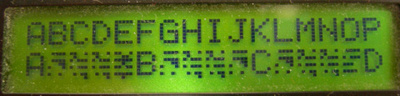
If I comment out the two marked lines below in the read procedure and include the other marked lines outside the read loop the bottom line of the display which is the string read from memory is identical to the top line:
Code: Select all
program EEPROM_SPI_25LC1024;

//******************************************************************************
// Program writes start of alphabet to a 25LC1024 eeprom, displays on line #1
//of LCD, then reads back the same bytes, displaying them on line #2 and
// EasydsPIC2 at FRC 7.37 MHz, dsPIC30F4013.

const
  CS_PIN_EEPROM           = 4;     //Chip enable pin portF
  //Commands
  EE_ReadCmd            = $03;     //read data from selected address
  EE_WriteCmd           = $02;     //write data to selected address
  EE_WriteEnable        = $06;     //set write enable latch (enable write ops)
  EE_WriteDisable       = $04;     //reset the write enable latch (disable write ops)
  EE_ReadStatusReg      = $05;     //read status register
  EE_WriteStatusReg     = $01;     //write status register
  EE_PageErase          = $42;     //page erase
  EE_SectorErase        = $D8;     //sector erase
  EE_ChipErase          = $C7;     //chip erase
  EE_RelDeepPowerDwn    = $AB;     //release from deep power down & read ID
  EE_DeepPowerDwn       = $B9;     //enter deep power down mode


var
   dataByte,dataReadByte : Word;
   Pos                  : Word;
   EEdataAddr           : LongInt;


procedure DeepPowerDwnEE;
begin
  while SPI1STAT.1 = 1 do                // wait for SPI module to finish, if doing something
   nop;
  LatF.CS_PIN_EEPROM := 0;
  Spi1_Write(EE_DeepPowerDwn);           // Deep power down
  while SPI1STAT.1 = 1 do                // Wait for SPI module to finish write
   nop;
  LatF.CS_PIN_EEPROM := 1;
end;

procedure RelDeepPowerDwnEE;
begin
  while SPI1STAT.1 = 1 do                // wait for SPI module to finish, if doing something
   nop;
  LatF.CS_PIN_EEPROM := 0;
  Spi1_Write(EE_RelDeepPowerDwn);        // Deep power down
  while SPI1STAT.1 = 1 do                // Wait for SPI module to finish write
   nop;
  LatF.CS_PIN_EEPROM := 1;
  Delay_us(200);
end;


procedure WriteInProgressPollEE;
//This routine loops until WIP:= 0
var
  Status: Byte;
begin

  while (Status and $01) do              //The WIP bit is bit 0.
    begin
      LATF.CS_PIN_EEPROM:= 0;             //Select Device
      SPI1_Write(EE_ReadStatusReg);       //Read Status Reg OpCode
      Status:= SPI1_Read(0);              //Read Status Reg
      LATF.CS_PIN_EEPROM:= 1;             //Deselect Device
    end;                                  //Check for WIP bit Set
end;


procedure WriteEnableEE;
begin
  while SPI1STAT.1 = 1 do                // wait for SPI module to finish, if doing something
   nop;
  LatF.CS_PIN_EEPROM := 0;
  Spi1_Write(EE_WriteEnable);            //enable writes
  while SPI1STAT.1 = 1 do                // Wait for SPI module to finish write
   nop;
  LatF.CS_PIN_EEPROM := 1;
end;


procedure WriteDisableEE;
begin
  while SPI1STAT.1 = 1 do                // Wait for SPI module to finish write
   nop;
  LatF.CS_PIN_EEPROM := 0;
  Spi1_Write(EE_WriteDisable);           //disable writes to eeprom
  while SPI1STAT.1 = 1 do                // Wait for SPI module to finish write
   nop;
  LatF.CS_PIN_EEPROM := 1;
end;


procedure WriteEEByte(databyte: Word; EEdataAddr:LongInt);
begin
  while SPI1STAT.1 = 1 do             // wait for SPI module to finish, if doing something
   nop;
  LatF.CS_PIN_EEPROM := 0;
  Spi1_Write(EE_WriteCmd);             //write command
  Spi1_Write(Higher(EEdataAddr));       //send 24 bit address
  Spi1_Write(Hi(EEdataAddr));
  Spi1_Write(Lo(EEdataAddr));
  Spi1_Write(databyte);               //write data
  LatF.CS_PIN_EEPROM := 1;
  WriteInProgressPollEE;
end;


function ReadEEByte(EEdataAddr: LongInt): Word;
begin
  while SPI1STAT.1 = 1 do             // wait for SPI module to finish, if doing something
    nop;
  LatF.CS_PIN_EEPROM := 0;                  //Comment out this to make it "work"
  Spi1_Write(EE_ReadCmd);            //issue the READ command
  Spi1_Write(Higher(EEdataAddr));     //send 24 bit address
  Spi1_Write(Hi(EEdataAddr));
  Spi1_Write(Lo(EEdataAddr));

  dataReadByte := SPI1_read(0);       //read the eeprom
  LatF.CS_PIN_EEPROM := 1;                  //Comment out this to make it "work"
  ReadEEByte:=dataReadByte;
end;


begin
  Delay_ms(500);
  ADPCFG := $FFFF;
  TRISD  := $FFF0;
  TrisB  := $000F;
  LatB:=0;
  TRISF.2 := 1;     //input
  TRISF.3 := 0;     //output
  TRISF.CS_PIN_EEPROM := 0;          // CS pin
  LatF.CS_PIN_EEPROM  := 1;          // Set CS to inactive

  //CS pins for other connected SPI devices, keep them quiet
  TRISF.0 := 0;     //input
  LatF.0  := 1;     //inactive
  TRISF.5 := 0;     //input
  LatF.5  := 1;     //inactive

 // SPI setup
  Spi1_Init_Advanced(_SPI_MASTER, _SPI_8_BIT, _SPI_PRESCALE_SEC_1, _SPI_PRESCALE_PRI_1,
                     _SPI_SS_DISABLE, _SPI_DATA_SAMPLE_MIDDLE, _SPI_CLK_IDLE_HIGH,
                     _SPI_ACTIVE_2_IDLE);
  // Spi1_Init;


  Lcd_Init(LATB, 7, 6, 5, 4, LATD, 0, 1, 2);
  Lcd_Cmd(LCD_CURSOR_OFF);
  Lcd_Cmd(LCD_CLEAR);

  RelDeepPowerDwnEE; //Just in case..

  Delay_ms(1000);


  //Write single bytes to external eeprom and display written chars on LCD
  EEdataAddr := 0;
  databyte := 65;
  WriteEnableEE;
  while EEdataAddr < 16 do begin
     WriteEEByte(databyte,EEdataAddr);
     Pos:=EEdataAddr+1;
    lcd_Chr(1,Pos,databyte);
    Inc(EEdataAddr);
    Inc(databyte);
  end;
  WriteDisableEE;

  Delay_ms(1000);
 //Read single bytes from external eeprom and display the chars on LCD
  EEdataAddr := 0;
  //LatF.CS_PIN_EEPROM := 0;            //Remove comment to make it "work"
  while EEdataAddr < 16 do begin
    dataReadByte:=ReadEEByte(EEdataAddr);
    delay_ms(10);
    Pos:=EEdataAddr+1;
    lcd_Chr(2,Pos,dataReadByte);
    Inc(EEdataAddr);
  end;
  //LatF.CS_PIN_EEPROM := 1;            //Remove comment to make it "work"

  //finished, do nothing more
  While true do begin
    nop;
  end;
end.From the data sheet of 25LC1024:
In other words, it should be possible to terminate read after a single byte. And if multiple reads are to be done sequentially the code should not resend the address as is the case in the commented out version that works.Read Sequence
The device is selected by pulling CS low. The 8-bit
READ instruction is transmitted to the 25LC1024
followed by the 24-bit address, with seven MSBs of the
address being “don’t care” bits. After the correct READ
instruction and address are sent, the data stored in the
memory at the selected address is shifted out on the
SO pin.
The data stored in the memory at the next address can
be read sequentially by continuing to provide clock
pulses. The internal Address Pointer is automatically
incremented to the next higher address after each byte
of data is shifted out. When the highest address is
reached (1FFFFh), the address counter rolls over to
address, 00000h, allowing the read cycle to be continued
indefinitely. The read operation is terminated by
raising the CS pin (Figure 2-1).
It would be very useful if someone with an in-ciruit debugger could try to reproduce it and find out what is going on...
