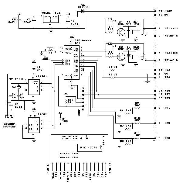
Hi, Historical note: I suspect that the original circuit is for a PIC16C54 type, and the microchip app notes did not have pull-up on one line. I think it was SDA.
If you want to stick with this chip it has no MSSP module, so you will have to use Soft_I2C routines.
If you have never I2C'd before, try somemthing simple first.
Get a PCF8574 port expander from Philips. Conncect pins A0,A1,A2 to 0v,
SDA and SCL to 5V through 10K resistors, 5V to VDD and 0v to VSS.
Connect SDA also to PIC portb,0 and SCL to pic portb,1.
Connect 8 LEDs anodes to 5v and with a 4.7K resistor in the cathode lead
connect the resitors to p0 thru p7 on the 8574.
Now you have to write a program!
Code: Select all
Const SlvAdd as byte = 0x40 'slave address
Dim Data_out, i  as byte

main:
Data_out = %11111110      '1s write port high, 0s write low
      Soft_I2C_Config(PORTB, 0, 1) ' defines b0 as SDA, b1 as SCL
for i = 0 to 7
'*******************************************************'from here

      Soft_I2C_Start                    'Have to send start
      Soft_I2C_Write(SlvAdd)       'then address write mode
      Soft_I2C_Write(Data_out)    'then data to send
      Soft_I2C_Stop                    'now we stop transmission

'*******************************************************'to here is an I2C  sequence
     delay_mS(500)                     'wait half second so we can see led lit
     Data_out = (Data_out) <<1  ' add 0 in next left spot
next i                                        'do it agin for next port pin

 While true
    nop
 wend   'just loops forever here with all 8 LEDS lit

end.
This simply lights the first LED then the next and next and so on until all 8 are on, but it should give you confidence with the use of SDA & SCL. Most important, download and read the datsheets for the PIC, the PCF8574 and the other chips you are using.