


Does Windows still cache descriptors? I seem to recall one USB "Gotcha" was that if you changed your descriptor then Linux boxes and Macs would use the new one but with Windows the old one had to be purged somehow before the new one would take effect? Does this still apply?
Also I think Microchip will issue one-off PIDs for use in PIC USB development.
PIC and USB
I found the by changing the vendor ID or PID the descriptor loads as a completely new device with Windows XP.
Peter, maybe we're overdriving the USB connection to the PC with the constant USB_Write command. Instead of putting the USB_Write command inside of a while loop, maybe only send data when necessary? I don't know what your application is, but maybe you can slow down the USB communication coming from the device. Just a thought.
Peter, maybe we're overdriving the USB connection to the PC with the constant USB_Write command. Instead of putting the USB_Write command inside of a while loop, maybe only send data when necessary? I don't know what your application is, but maybe you can slow down the USB communication coming from the device. Just a thought.
Hi Roy
Thank you for your info ,you are now the second person telling me to slow down the HID coms ,I will give it a go tomorrow
this is concerning when it is the case then HID is much slower than
Rs 232 ,I have gone back to the old Rs 232 coms and it is running fine
However below is a piece of the code I can not post all as it is confidential !!
you will see that I control the HID transmission with a Timer0 as low priority Interrupt and then count 30 mSec tick
then HID transmission is done The High priority interrupt still handles the normal HID as in mE examples
Thank you for your interest to help me highly appreciated
Peter
Code: Select all
program REX_Control_USB
'-----------------------------------------------------------------------
include USBdsc
include Configure
include CAN_Tx
'-----------------------------------------------------------------------
'Symbols
'-----------------------------------------------------------------------
'Global Variables
'-----------------------------------------------------------------------
Dim TxTick as byte       'Control Flag for 10mSec Counter
Dim Tx_Ready as byte     'Set when Time to Tx CAN
Dim HID_TxReady as byte  'Set when PC allows Coms
Dim HIDCount as byte
Dim TxLedCount as byte
Dim RxLedCount as byte
Dim Tx_Allowed As byte  'Set to allow CAN Tx
'-----------------------------------------------------------------------
'HID Interrupt
'----------------------------------------------------------------------
sub procedure interrupt
  HID_InterruptProc
end sub
'************************************************************
'Timer 0 Interrupt every 1mSec for Tx counter
'************************************************************
sub procedure  interrupt_low
  if(INTCON.TMR0IF = 1)Then
     T0CON.TMR0ON = 0
     INTCON.TMR0IF = 0
     TMR0H = 0xE8
     TMR0L = 0x77
     T0CON.TMR0ON = 1
     TxTick  = TxTick  + 1
     inc( HIDCount)
  '----------------------------------------------------------
  ' allow Msg Tx every 10mSec
  '-----------------------------------------------------------
  if(TxTick = 10) Then
     Tx_Ready  = 1
     TxTick = 0
  end if
  '----------------------------------------------------------
  'Allow USB  Transfer every 30mSec
  '---------------------------------------------------------
  if(HIDCount = 30)Then
      HID_TxReady  = 1
      HIDCount = 0
  end if
 end if
end sub
'----------------------------------------------------------------------
'Main Code Loop
'----------------------------------------------------------------------
main:
'------------------------------------------------------------
' initialize HID  Connect to PC
'------------------------------------------------------------
  HID_Enable(@userRD_buffer, @userWR_buffer)
  Delay_ms(1000)
  Delay_ms(1000)
  '------------------------------------------------------------
'Initializes the Micro Controller  and Clear Flags
'-----------------------------------------------------------
  Init()
  LATD.0 = 1
  LATD.1 = 1
  LATA.5 = 1
  TxTick = 0
  HIDCount = 0
  HID_TxReady = 0
'----------------------------------------------------------------------
while True
'----------------------------------------------------------------------
'Read CAN Msg's
'----------------------------------------------------------------------
  Msg_Rcvd = CANSPIRead(Rx_ID,Rx_Data,Rx_Data_Len,Can_Rcv_Flags)
if(Msg_Rcvd <> 0) Then
       Msg_Rcvd = 0   'Clear Message received Flag

 select case Rx_ID
 '----------------------------------------------------------------------
 ' Msg VCU_B1
 '----------------------------------------------------------------------
   Case 0x3E0
        inc(RxLedCount)
        if(RxLedCount = 5) Then
             LATD.1 = PORTD.1 Xor 1
             RxLedCount = 0
         end if
        userWR_buffer [37] = Rx_Data[3]'TPD Position in Kwatt
 '----------------------------------------------------------------------
 'Msg VCU_DBG3
 '----------------------------------------------------------------------
   Case 0x3E2
        userWR_buffer [0] = Rx_Data[0]  'Status bits
        userWR_buffer [1] = Rx_Data[4]  'TP Act Position
'---------------------------------------------------------------------
'   Msg  DMC2_Act
'---------------------------------------------------------------------
   Case 0x25C
        userWR_buffer [6] = Rx_Data[0] 'DC Voltage Hi byte
        userWR_buffer [7] = Rx_Data[1] 'DC Voltage Low byte
        userWR_buffer [4] = Rx_Data[2] 'DC Current Hi byte
        userWR_buffer [5] = Rx_Data[3] 'DC Current Low byte
        userWR_buffer [2] = Rx_Data[4] 'AC current Hi byte
        userWR_buffer [3] = Rx_Data[5] 'AC current low byte
        userWR_buffer [8] = Rx_Data[6] 'MPower Hi byte
        userWR_buffer [9] = Rx_Data[7] 'Mpower Low byte
'---------------------------------------------------------------------
'       DMC2_TQRS
'---------------------------------------------------------------------
   Case 0x25B
        userWR_buffer [10] = Rx_Data[6] 'Gen Act speed Hi Byte
        userWR_buffer [11] = Rx_Data[7] 'Gen Act speed low byte
        userWR_buffer [12] = Rx_Data[0] 'Gen Warn/errors start bit 56
        userWR_buffer [13] = Rx_Data[1] 'gen warn/errors Start bit 47
        userWR_buffer [14] = Rx_Data[4] 'Gen TrqAct Hi byte
        userWR_buffer [15] = Rx_Data[5] 'Gen TrqAct Low byte
 '--------------------------------------------------------------------
 'Msg DMC TRQS (Motor )
 '--------------------------------------------------------------------
   case 0x258
        userWR_buffer [32] = Rx_Data[6] 'DMC Speed Act Hi byte(motor)
        userWR_buffer [33] = Rx_Data[7] 'DMC Speed Act Low Byte (motor)
        userWR_buffer [34] = Rx_Data[4] 'DMC Trq Act Hi Byte (motor)
        userWR_buffer [35] = Rx_Data[5] 'DMC Trq Act Low Byte(motor)
'---------------------------------------------------------------------
'       DMC _ACt Values(motor)
'--------------------------------------------------
  Case 0x259
        userWR_buffer [24] = Rx_Data[6] 'DMC mech Power Hi Byte
        userWR_buffer [25] = Rx_Data[7] 'DMC Mech Power Low Byte
        userWR_buffer [26] = Rx_Data[4] 'DMC Ac Current Hi Byte
        userWR_buffer [27] = Rx_Data[5] 'DMC Ac Current Low Byte
        userWR_buffer [28] = Rx_Data[2] 'DMC Dc Current Hi Byte
        userWR_buffer [29] = Rx_Data[3] 'DMC Dc Current Low Byte
        userWR_buffer [30] = Rx_Data[0] 'DMC Dc Voltage Hi Byte
        userWR_buffer [31] = Rx_Data[1] 'DMC Dc Voltage Low Byte
'---------------------------------------------------------------------
'      BATT_Act
'---------------------------------------------------------------------
  Case 0x110
        userWR_buffer [16] = Rx_Data[0] 'Batt Voltage Hi byte
        userWR_buffer [17] = Rx_Data[1] 'Batt Voltage low byte
        userWR_buffer [18] = Rx_Data[2] 'Batt Current Hi byte
        userWR_buffer [19] = Rx_Data[3] 'Batt Current Low byte
        userWR_buffer [20] = Rx_Data[4] 'Batt Temp Hi byte
        userWR_buffer [21] = Rx_Data[5] 'Batt Temp Low byte
        userWR_buffer [22] = Rx_Data[6] 'Batt DoD Hi byte
        userWR_buffer [23] = Rx_Data[7] 'Batt DoD Low byte
'---------------------------------------------------------------------
 end Select
 end if
'---------------------------------------------------------------------
'Send received CAN Data to PC every 30mSec
'---------------------------------------------------------------------
  if(HID_TxReady <>0)Then
       HID_TxReady  = 0
   if(Tx_Allowed = 0x0A ) Then
          HID_Write(@userWR_buffer,64)
   end if
  end if
'----------------------------------------------------------------------
'Send VCU_COM Msg every 10mSec
'----------------------------------------------------------------------
 if(Tx_Ready<>0) Then
      Tx_Ready  = 0  'Clear 10mSec counter
   if(Tx_Allowed = 0x0A) Then
     Msg_VCU_COM()   'Send Control Message
   end if
 end if
 '---------------------------------------------------------------------
 'Read USB and Process if Necessary
 '---------------------------------------------------------------------
    k = HID_Read()
 if(k <> 0) Then
      LATA.5 = PORTA.5 Xor 1
      Tx_Data[0] = userRD_buffer[0]
      Tx_Data[1] = userRD_buffer[1]
      Tx_Data[2] = userRD_buffer[2]
      Tx_Data[3] = userRD_buffer[3]
      Tx_Data[4] = userRD_buffer[4]
      Tx_Data[5] = userRD_buffer[5]
      Tx_Data[6] = userRD_buffer[6]
      Tx_Data[7] = userRD_buffer[7]
      Tx_Allowed = userRD_buffer[8]
  end if
wend
     HID_Disable()
end.
P.Erasmus
Saratov,Russia
--------------------------------------------------------------
Saratov,Russia
--------------------------------------------------------------
Roy
I reduced the Transmition rate to 140 mSec today and it seems to help
as I was running the application 2 X for about 30 min each with no Hanging of windows ,what you say seems to be totaly correct
changing the rate or break the data up into smaller pieces is going to help me
at least the application is no running stable you really helped me to go forward roy thanks a million
Peter
I reduced the Transmition rate to 140 mSec today and it seems to help
as I was running the application 2 X for about 30 min each with no Hanging of windows ,what you say seems to be totaly correct
changing the rate or break the data up into smaller pieces is going to help me
Peter
P.Erasmus
Saratov,Russia
--------------------------------------------------------------
Saratov,Russia
--------------------------------------------------------------
Roy
The application is stable with the slower transmission speed ,
However I will let you know the final out come ,
I am flying to South Africa on the 10th and I will only work on this again in January 2010 .
I agree the forum is a good idea and a place we peopel can help each other ,
Have a nice time
Peter
P.Erasmus
Saratov,Russia
--------------------------------------------------------------
Saratov,Russia
--------------------------------------------------------------
USB JOYSTICK with 18f4550
hello,
is' t possible for those that have good result on usb card with 32 button and 8 joystick, on Mikro C or Mikro Basic to share our result.
i have try to build but with good result
cheers
patrice
is' t possible for those that have good result on usb card with 32 button and 8 joystick, on Mikro C or Mikro Basic to share our result.
i have try to build but with good result
cheers
patrice
Re: 18F4550 and Roys29 DRA interface
I have tried the software (DRA Interface) but am having a few problems
I have had to reinstall MBPro2.5 I am using PIC18F4550 not 2450
I have made a custom board with 12Mhz
- divide by 3 (12mhz)
- [OSC1/OSC2 Src:/1][96Mhz PLL/2]
-Clock src from 96Mhz PLL/2
- HS:HS+PLL, USB-HS
-
USB Voltage reg' ENABLED
When I plug in USB, windows says 'USB Device not recognized'
PIC is running as it can cycle an LED etc
any help would be good
Sorted
Cut the D+ & D- wires on the USB cable shorter and twisted them
Steve
Re: PIC and USB
Hi Steve,
I had that same error message when my descriptor file was incorrect. It would help if you post your descriptor file so we can look at it. My problem turned out to be the fact that I didn't declare exact multiples of 8 bytes for an HID device. Once I got the USB device descriptor right, it worked. I will check my DRA interface again, but that one did work at 8 MHz with version 2.50.
I had that same error message when my descriptor file was incorrect. It would help if you post your descriptor file so we can look at it. My problem turned out to be the fact that I didn't declare exact multiples of 8 bytes for an HID device. Once I got the USB device descriptor right, it worked. I will check my DRA interface again, but that one did work at 8 MHz with version 2.50.
Re: PIC and USB
Roy
We have sorted all that end, it was a simple silly fault, NOT your DRA file.
We are using a 4550 at 12mhz. on a custom etched PCB.
My son is building the project for his A levels.
He is building a Boeing 737 something or other with levers, switches, buttons, paddles etc
I will post a picture when it is done - in next 3 weeks.
You mention you are using some ON/OFF switches, same here also, these work OK when turning on - the pulse goes though, but you don't get another pulse when it is turned off, so for landing lights etc the switch on FSX PC screen moves down and the lights come on, when the switch is turned off, nothing, he needs to turn it back on the FSX screen switched back up (off) and the lights go off.
That is his next part to write that into the software, he also wants some momentary switches to stay on while the switch is pressed, again he is going to re write that part.
Steve
Re: PIC and USB
Hi Steve,
Yup, I also created a switch interface for use with Microsoft Flight Simulator. If I remember correctly, for toggle switches I had to use SPDT switches with the NO/NC connections tied together to a row connection, and the common to a column connection. In this way toggling the switch up or down would trigger the pulse, and it did have to be a pulse! I have some other code I can provide for pulses if you're interested.
Roy
Re: PIC and USB
Hi roys !
I'd like to download you pdf file about the joystick, but the link is down.
Could you repost the document please ?
Thanks
Matoms
I'd like to download you pdf file about the joystick, but the link is down.
Could you repost the document please ?
Thanks
Matoms
Re: PIC and USB
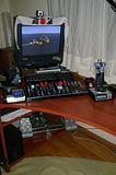
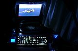
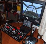
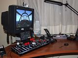
Roy, 1M THANKS for sharing your project and knowledge!
I have been a dedicated flight-simmer for the past 3 years too. I have build my own pedals, my own head-tracking and my own flight console, all using pre-made PIC-based USB controllers, so I have come to the point to build my own controller..
I used the example from your "JOYSTICK CONVERSION" but had no luck at all! I could not even compile it!
I am using MikroBasic PRO v3.8, but when i am compiling the "F16_JOYSTICK.mbas" and "f16_desc.mbas" i get this error:
Any ideas why this is happening?
THANK YOU!
PS: Here are some pictures of my sim-pit:
And a Youtube video:
http://www.youtube.com/user/StergiosDS# ... Q4bmXHg69g
I have been a dedicated flight-simmer for the past 3 years too. I have build my own pedals, my own head-tracking and my own flight console, all using pre-made PIC-based USB controllers, so I have come to the point to build my own controller..
I used the example from your "JOYSTICK CONVERSION" but had no luck at all! I could not even compile it!
I am using MikroBasic PRO v3.8, but when i am compiling the "F16_JOYSTICK.mbas" and "f16_desc.mbas" i get this error:
Code: Select all
0 1 mBPic.exe -DBG -pP18F2455 -MSF -Y -DL -O11111114 -fo48 -N"D:\Stergios\ÄéÜöïñá\PIC\%Projects Library\PIC18F2455 joystick_conversion_MikroBasic\F16_Joystick.mbppi" -SP"C:\Program Files\Mikroelektronika\mikroBasic PRO for PIC\defs\" -SP"C:\Program Files\Mikroelektronika\mikroBasic PRO for PIC\uses\P18\" -SP"D:\Stergios\ÄéÜöïñá\PIC\%Projects Library\PIC18F2455 joystick_conversion_MikroBasic\" -SP"C:\Documents and Settings\RSeifert\My Documents\Roy\PIC18 Programming\Projects\F16_Joystick\" -SP"C:\Documents and Settings\RSeifert\My Documents\Roy\PIC18 Programming\Projects\DRA_Interface\" -SP"C:\Documents and Settings\RSeifert\My Documents\Roy\PIC18 Programming\Projects\Copy of Switch_Interface\" -SP"C:\Documents and Settings\RSeifert\My Documents\Roy\PIC18 Programming\Projects\Switch_Interface\" "__Lib_Math.mcl" "__Lib_MathDouble.mcl" "__Lib_System.mcl" "__Lib_Delays.mcl" "__Lib_ADC_A_D.mcl" "__Lib_USB_genHID.mcl" "F16_Joystick.mbas"

0 1501 Specified search path does not exist: 'C:\Documents and Settings\RSeifert\My Documents\Roy\PIC18 Programming\Projects\F16_Joystick'

0 1501 Specified search path does not exist: 'C:\Documents and Settings\RSeifert\My Documents\Roy\PIC18 Programming\Projects\DRA_Interface'

0 1501 Specified search path does not exist: 'C:\Documents and Settings\RSeifert\My Documents\Roy\PIC18 Programming\Projects\Copy of Switch_Interface'

0 1501 Specified search path does not exist: 'C:\Documents and Settings\RSeifert\My Documents\Roy\PIC18 Programming\Projects\Switch_Interface'

0 155 Available RAM: 2027 [bytes], Available ROM: 24576 [bytes]

0 133 Compilation Started D:\Stergios\ÄéÜöïñá\PIC\%Projects Library\PIC18F2455 joystick_conversion_MikroBasic\F16_Joystick.mbas

1 1015 Hint: Compiling unit "D:\Stergios\ÄéÜöïñá\PIC\%Projects Library\PIC18F2455 joystick_conversion_MikroBasic\F16_Joystick.mbas" F16_Joystick.mbas

1 1015 Hint: Compiling unit "D:\Stergios\ÄéÜöïñá\PIC\%Projects Library\PIC18F2455 joystick_conversion_MikroBasic\f16_desc.mbas" f16_desc.mbas

17 303 Identifier "USB_CONFIG_DESCRIPTOR_LEN" was not declared f16_desc.mbas

18 301 "+"is not valid identifier f16_desc.mbas

18 304 Syntax error: Expected "end" but "+" found f16_desc.mbas

18 304 Syntax error: Expected "." but "USB_INTERF_DESCRIPTOR_LEN" found f16_desc.mbas

49 307 File "f16_desc.mcl" not found F16_Joystick.mbas

0 102 Finished (with errors): 15 Éïõë 2010, 19:45:06 F16_Joystick.mbppi
THANK YOU!
PS: Here are some pictures of my sim-pit:


And a Youtube video:
http://www.youtube.com/user/StergiosDS# ... Q4bmXHg69g
My simulation cockpit and other projects: www.numca.gr
