I found a sample code on the Internet, but it is not working properly.
Will anyone help me to correct this code?
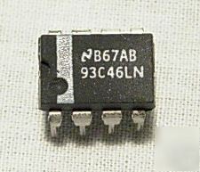
I connected the 93C46LN as follows:
Vcc <-> 5V
GND <-> GND
CS <-> RB4
SK <-> RB1 (SCK)
DI <-> RB0 (SDI)
TO <-> RB3 (SDO)
250kHz SPI (microwire) frequency (FOSC INTOSC 1MHz / 4).
MicroC PRO For PIC Code (for
PIC18F25K50)
Code: Select all
// for simplicity define the instructions 93C46LN
#define READ      0x02   // read data                                             //00000010 (93C46LN opcode)
#define WRITE     0x01   // Write data                                            //00000001 (93C46LN opcode)
#define WREN      0x00   // Set write enable latch                                //00000000 (93C46LN opcode)
//#define WRDI      0x04   // Reset write enable latch
//#define RDSR      0x05   // read STATUS register
//#define WRSR      0x01   // write STATUS register

// define your #CS & #HOLD (if used) here!
sbit  SPI_EEPROM_CS  at RB4_bit;
sbit  SPI_EEPROM_CS_Direction at TRISB4_bit;


void spi_eeprom_write_byte(int address, unsigned char value)
{
      unsigned char tempchar = 0;

       SPI_EEPROM_CS = 0;             // enable
       tempchar = SPI1_Read(WREN);    // enable write
       SPI_EEPROM_CS = 1;             // disable
       Delay_us(100);
       SPI_EEPROM_CS = 0;             // enable
       //write instruction
       tempchar = SPI1_Read(WRITE);   // write
       // write address
       tempchar = SPI1_Read((unsigned char)address > 8);
       tempchar = SPI1_Read((unsigned char)address & 0x0F);
       //write byte
       tempchar = SPI1_Read(value);
       SPI_EEPROM_CS = 1;             // disable
       asm nop;
}

unsigned char spi_eeprom_read_byte(int address)
{
      unsigned char tempchar = 0;

     SPI_EEPROM_CS = 0;             // enable
     SPI1_Write(READ);    // write instruction
     // write address
     SPI1_Write((unsigned char)address > 8);
     SPI1_Write((unsigned char)address & 0x0F);
     //read byte
     tempchar = SPI1_Read(0);
     SPI_EEPROM_CS = 1;             // disable
     asm nop;
     return tempchar;
}

/*
unsigned char spi_eeprom_read_byte(int address)
{
      unsigned char tempchar = 0;

     SPI_EEPROM_CS = 0;             // enable
     tempchar = SPI1_Read(READ);    // write instruction
     // write address
     tempchar = SPI1_Read((unsigned char)address > 8);
     tempchar = SPI1_Read((unsigned char)address & 0x0F);
     //read byte
     tempchar = SPI1_Read(0);
     SPI_EEPROM_CS = 1;             // disable
     asm nop;
     return tempchar;
}*/

void init()
{
     OSCCON  = 0b00110000;              // 1MHz INTOSC
     OSCTUNE = 0b00000000;
     ANSELB  = 0x00;
     ANSELB  = 0x00;                    // PORTB digital olny
     ANSELC  = 0x00;                    // PORTC digital olny
     SPI_EEPROM_CS_Direction = 0;
     //TRISC.F6 = 0;                    // RC6 out
}

void main()
{
     init();
     UART1_Init(9600);                  // UART1 init
     SPI1_Init();                       // Initialize SPI module

     spi_eeprom_write_byte(0x00, 0x58);
     spi_eeprom_write_byte(0x02, 0x59);
     spi_eeprom_write_byte(0x04, 0x56);

     Delay_ms(100);

     while(1)
     {
          Delay_ms(1000);

          UART1_Write(spi_eeprom_read_byte(0x00));

          UART1_Write(spi_eeprom_read_byte(0x02));

          UART1_Write(spi_eeprom_read_byte(0x04));

          UART1_Write(spi_eeprom_read_byte(0x06));

          UART1_Write(spi_eeprom_read_byte(0x08));

     }
}
The UART console displays the following information (I have uploaded the code above):