20%
OFF
GO LOCAL
| Company | Stock | Price |
|---|---|---|

MIKROE-1135
38 g
Status:
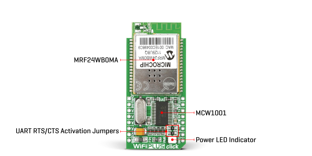
WiFi Plus Click is a compact add-on board providing a low-power WiFi solution. This board features the MRF24WB0MA, a 2.4GHz, IEEE standard 802.11b/g/n compliant RF transceiver from Microchip. The MRF24WB0MA comes with an integrated antenna, with a range of up to 400m, and a place for a u.Fl connector. It is characterized by low power consumption and built-in hardware support for AES and TKIP (WEP, WPA, and WPA2 security). WiFi Plus Click also features an MCW1001 companion controller, also from Microchip, with an onboard TCP/IP stack and 802.11 connection manager, which in combination with MRF24WB0MA, results in support for IEEE Standard 802.11 and IP services. This Click board™ is suitable for highly integrated and cost-effective applications, industrial wireless control, smart home applications, utility and smart energy, remote device management, and more.
WiFi Plus Click is supported by a mikroSDK compliant library, which includes functions that simplify software development. This Click board™ comes as a fully tested product, ready to be used on a system equipped with the mikroBUS™ socket.
This product is no longer in stock
Availability date:
20%
OFF
| Company | Stock | Price |
|---|---|---|

WiFi Plus Click is based on the MRF24WB0MA, a 2.4GHz, IEEE standard 802.11b/g/n compliant WiFi module from Microchip. The MRF24WB0MA uses a 4-wire SPI interface with an interrupt feature, has 14 channels selectable individually or domain-restricted, and DSSS Modulation. With a data rate of 1000Kbps and -91dBm sensitivity at 1Mbps, integrated low-phase noise digital VCO, RF frequency synthesizer, PLL loop filter, and PA, it makes a perfect solution for WiFi applications. As for MAC, the MRF24WB0MA features automatic MAC packet retransmit, hardware CSMA/CA access control, automatic ACK, FCS creation and checking, WEP, WPA-PSK, WPA2-PSK security, and more.

Considering that the MRF24VB0MA does not have a hardware TCP/IP stack, for this reason, another component is added to this Click board™, the MCW1001, a companion controller with an on-board TCP/IP stack and 802.11 connection manager also from Microchip. The MCW1001 has built-in WiFi connection management messages and operates seamlessly with the MRF24WB0MA over the 4-wire SPI interface. Apart from their communication, the MCW1001 also controls other features of the main module, such as access to hibernation mode, write protection, reset, and interrupt. On the other hand, for its communication with the host MCU, the MCW1001 uses the UART interface with commonly used UART RX/TX pins and hardware flow control pins UART CTS and RTS (Clear to Send, and Ready to Send). These optional signals can be used by setting the J1 and J2 jumpers.
Additional options this board has are other used pins of the mikroBUS™ socket. In addition to the already mentioned Reset feature, this Click board also uses three GP pins (GP0, GP1, GP2), routed to the AN, PWM, and INT pins of the mikroBUS™ socket, giving them access to a general purpose I/Os of the MCW1001.
This Click board™ can be operated only with a 3.3V logic voltage level. The board must perform appropriate logic voltage level conversion before using MCUs with different logic levels. However, the Click board™ comes equipped with a library containing functions and an example code that can be used, as a reference, for further development.
Type
WiFi
Applications
Can be used for highly integrated and cost-effective applications, industrial wireless control, smart home applications, utility and smart energy, remote device management, and more
On-board modules
MRF24WB0MA - 2.4GHz RF transceiver from Micriochip
MCW1001 - controller with an on-board TCP/IP stack and 802.11 connection manager from Microchip
Key Features
Low power consumption, range up to 400m, integrated printed 2.4GHz antenna (u.Fl optional), WiFi alliance certifications, compatible with IEEE 82.11b/g/n networks, UART interface, reset and additional GP signals, and more
Interface
GPIO,UART
Feature
No ClickID
Compatibility
mikroBUS™
Click board size
M (42.9 x 25.4 mm)
Input Voltage
3.3V
Category
Click Boards
This table shows how the pinout on WiFi Plus Click corresponds to the pinout on the mikroBUS™ socket (the latter shown in the two middle columns).
| Label | Name | Default | Description |
|---|---|---|---|
| LD1 | PWR | - | Power LED Indicator |
| J1 | J1 | Populated | UART RTS Activation Jumper |
| J2 | J2 | Populated | UART CTS Activation Jumper |
| Description | Min | Typ | Max | Unit |
|---|---|---|---|---|
| Supply Voltage | - | 3.3 | - | V |
| Operating Frequency Range | - | 2.4 | - | GHz |
NOTE: Please be advised that any peripheral devices or accessories shown connected to the Click board™ are not included in the package. Check their availability in our shop or in the YMAN section below.