


OFF
GO LOCAL
| Company | Stock | Price |
|---|---|---|


MIKROE-4288
20 g
Status:
RTC 11 Click is a compact add-on board that contains a real-time clock IC designed to maximize battery life and reduce overall battery requirements in wearable applications. This board features the AB0815, an ultra-low-power coupled with a highly sophisticated feature set the real-time clock from Abracon LLC. The AB0815 includes on-chip oscillator to provide low power consumption, full RTC functions such as battery backup, programmable counters, and alarms for timer and watchdog functions. Its power requirements are lower than any other industry RTC (as low as 22 nA) and communicate with MCU using the SPI interface. This Click board™ is suitable for applications such as portable applications, wearables, medical equipment, and similar.
RTC 11 Click is supported by a mikroSDK compliant library, which includes functions that simplify software development. This Click board™ comes as a fully tested product, ready to be used on a system equipped with the mikroBUS™ socket.
This product is no longer in stock
Availability date:
OFF
| Company | Stock | Price |
|---|---|---|
RTC 11 Click is based on the AB0815, an ultra-low-power coupled with a highly sophisticated feature set, the real-time clock from Abracon LLC. The AB0815 serves as a full-function RTC and includes 3 feature groups: baseline and advanced timekeeping features, and power management. Functions from each feature group may be controlled via I/O offset mapped registers accessed through SPI serial interface. The baseline timekeeping feature group supports the standard 32.786 kHz crystal oscillation mode for maximum frequency accuracy with an ultra-low current draw of 22nA. This feature also includes a standard set of counters for minutes, hours, dates, months, years, and week-days. A complement of countdown timers and alarms may additionally be set to initiate interrupts or resets on several of the outputs.
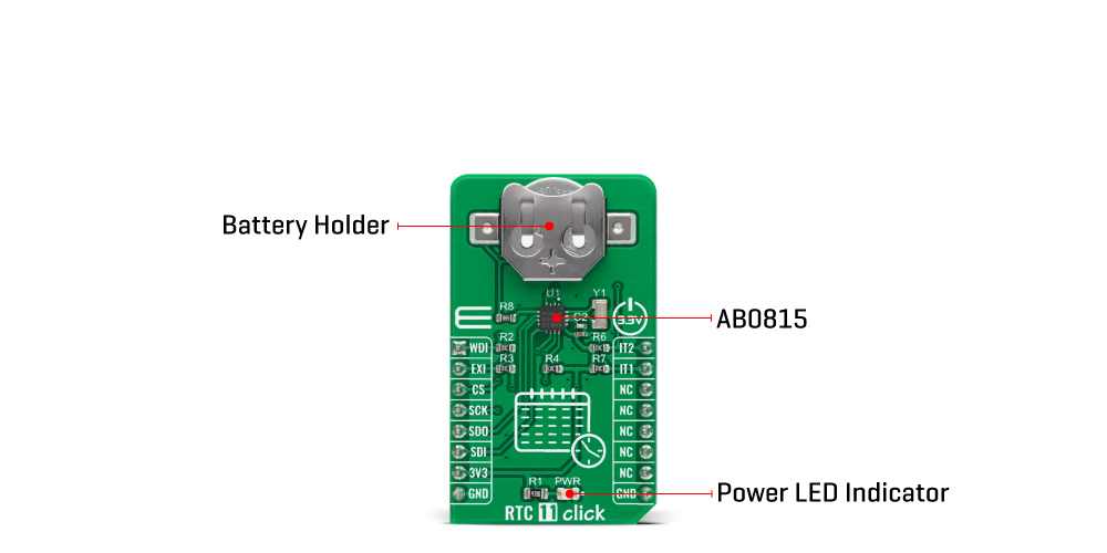
The most common configuration as performed on this Click board™ is a battery backed up RTC, which maintains time and may hold data in RAM. In addition to the AB0815, the RTC 11 Click is equipped with the button cell battery holder compatible with the 3000TR battery holder, suitable for 12mm Coin Cell batteries. By utilizing an automatic backup switch, the AB0815 can use an external battery power source when there is no power supply on its main power terminals, thus allowing for uninterrupted operation.
The AB0815 communicates with MCU using the standard SPI serial interface that supports modes 0 and 3 with a maximum frequency of 2 MHz. The flexible inputs of the AB0815 can be used to aggregate a variety of interrupt sources, including external digital inputs, analog levels, timers, and alarms into a single interrupt source to an MCU. Based on this, functions like external interrupt or watchdog timer reset could be found on this Click board™ routed on the RST and AN pins of the mikroBUS™ socket labeled as EXI and WDI, as well as the primary and secondary interrupt outputs routed on the INT and PWM pins of the mikroBUS™ socket labeled as IT1 and IT2.
This Click board™ is designed to be operated only with a 3.3V logic voltage level. A proper logic voltage level conversion should be performed before the Click board™ is used with MCUs with different logic levels. However, the Click board™ comes equipped with a library that contains easy to use functions and an example code that can be used as a reference for further development.
Type
RTC
Applications
Can be used for applications such as portable applications, wearables, medical equipment, and similar.
On-board modules
RTC 11 Click is based on the AB0815, an ultra-low-power coupled with a highly sophisticated feature set, the real-time clock from Abracon LLC.
Key Features
Low power consumption, battery backup, programmable counters, alarms for timer and watchdog functions, and more.
Interface
SPI
Feature
No ClickID
Compatibility
mikroBUS™
Click board size
M (42.9 x 25.4 mm)
Input Voltage
3.3V
This table shows how the pinout on RTC 11 Click corresponds to the pinout on the mikroBUS™ socket (the latter shown in the two middle columns).
| Notes | Pin | Pin | Notes | ||||
|---|---|---|---|---|---|---|---|
| Watchdog Timer Reset | WDI | 1 | AN | PWM | 16 | IT2 | Secondary Interrupt |
| External Interrupt | EXI | 2 | RST | INT | 15 | IT1 | Primary Interrupt |
| SPI Chip Select | CS | 3 | CS | RX | 14 | NC | |
| SPI Clock | SCK | 4 | SCK | TX | 13 | NC | |
| SPI Data OUT | SDO | 5 | MISO | SCL | 12 | NC | |
| SPI Data IN | SDI | 6 | MOSI | SDA | 11 | NC | |
| Power Supply | 3.3V | 7 | 3.3V | 5V | 10 | NC | |
| Ground | GND | 8 | GND | GND | 9 | GND | Ground |
| Label | Name | Default | Description |
|---|---|---|---|
| LD1 | PWR | - | Power LED Indicator |
| Description | Min | Typ | Max | Unit |
|---|---|---|---|---|
| Supply Voltage | -0.3 | 3.3 | 3.8 | V |
| Battery Supply Voltage | 1.4 | - | 3.6 | V |
| Maximum Output Current | -20 | - | 20 | mA |
| SPI Clock Frequency | - | - | 2 | MHz |
| Operating Temperature Range | -40 | - | +85 | °C |
We provide a library for the RTC 11 Click on our LibStock page, as well as a demo application (example), developed using MikroElektronika compilers. The demo can run on all the main MikroElektronika development boards.
Library Description
The library covers all the necessary functions that enables the usage of the RTC 11 Click board. User can set or read time, date, day of the week, alarm, change settings, or use generic read and write functions.
Key functions:
void rtc11_set_time ( uint8_t t_hrs, uint8_t t_min, uint8_t t_sec ); - Function is used to set system time.void rtc11_get_time ( uint8_t *t_hrs, uint8_t *t_min, uint8_t *t_sec ); - Function is used to get current system time.void rtc11_get_date ( uint8_t *w_day, uint8_t *d_day, uint8_t *d_mon, uint8_t *d_yrs ); - Function is used to get system date.Examples description
The application is composed of three sections :
void application_task ( )
{
    rtc11_get_time ( &t_hrs, &t_min, &t_sec );
    Delay_ms( 10 );
    rtc11_get_date ( &w_day, &d_day, &d_mon, &d_yrs );
    Delay_ms( 10 );
    if ( sec_flag != t_sec )
    {
        mikrobus_logWrite( " Time: ", _LOG_TEXT );
        ByteToStr( t_hrs, log_txt );
        ltrim( log_txt );
        mikrobus_logWrite( log_txt, _LOG_TEXT );
        mikrobus_logWrite( ":", _LOG_TEXT );
        ByteToStr( t_min, log_txt );
        ltrim( log_txt );
        mikrobus_logWrite( log_txt, _LOG_TEXT );
        mikrobus_logWrite( ":", _LOG_TEXT );
        ByteToStr( t_sec, log_txt );
        ltrim( log_txt );
        mikrobus_logWrite( log_txt, _LOG_TEXT );
        mikrobus_logWrite( "", _LOG_LINE );
        mikrobus_logWrite( " Date: ", _LOG_TEXT );
        disp_day_of_the_week( w_day );
        mikrobus_logWrite( "/", _LOG_TEXT );
        ByteToStr( d_day, log_txt );
        ltrim( log_txt );
        mikrobus_logWrite( log_txt, _LOG_TEXT );
        mikrobus_logWrite( "/", _LOG_TEXT );
        ByteToStr( d_mon, log_txt );
        ltrim( log_txt );
        mikrobus_logWrite( log_txt, _LOG_TEXT );
        mikrobus_logWrite( "/", _LOG_TEXT );
        ByteToStr( d_yrs, log_txt );
        ltrim( log_txt );
        mikrobus_logWrite( "20", _LOG_TEXT );
        mikrobus_logWrite( log_txt, _LOG_TEXT );
        mikrobus_logWrite( "/", _LOG_TEXT );
        mikrobus_logWrite( "", _LOG_LINE );
    }
    sec_flag =  t_sec;
}
Additional Function :
The full application code, and ready to use projects can be found on our LibStock page.
Other mikroE Libraries used in the example:
Additional notes and informations
Depending on the development board you are using, you may need USB UART click, USB UART 2 click or RS232 click to connect to your PC, for development systems with no UART to USB interface available on the board. The terminal available in all MikroElektronika compilers, or any other terminal application of your choice, can be used to read the message.
This Click board™ is supported with mikroSDK - MikroElektronika Software Development Kit. To ensure proper operation of mikroSDK compliant Click board™ demo applications, mikroSDK should be downloaded from the LibStock and installed for the compiler you are using.
For more information about mikroSDK, visit the official page.
NOTE: Please be advised that any peripheral devices or accessories shown connected to the Click board™ are not included in the package. Check their availability in our shop or in the YMAN section below.

$889.00

$95.00

$549.00

$299.00

$29.00

$29.00

$3.30

$3.60

$119.00

$449.00

$349.00

$349.00

$349.00

$299.00

$269.00

$249.00

$209.00
