


OFF

MIKROE-6622
22 g
Status:
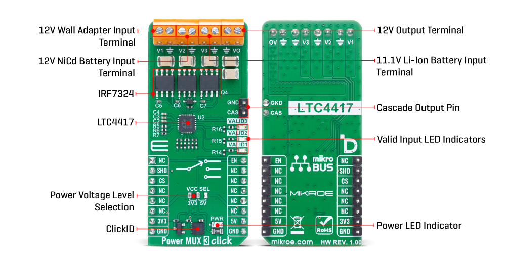
Power MUX 3 Click is a compact add-on board designed to manage multiple power sources in systems requiring high availability and power switching. It is based on the LTC4417, a prioritized PowerPath™ controller from Analog Devices that autonomously selects and connects one of up to three valid power supplies to a common output based on predefined priority (user-defined undervoltage and overvoltage thresholds for at least 256ms). The board uses only EN and SHD control pins, supports cascading via the CAS pin for expanded configurations, and features fast non-overlap switching, inrush current control, gate protection for onboard MOSFETs (IRF7324), and red VALID LED indicators for each channel. This Click board™ is ideal for battery backup systems, industrial handheld instruments, high-availability devices, and server peripherals.
Power MUX 3 Click is fully compatible with the mikroBUS™ socket and can be used on any host system supporting the mikroBUS™ standard. It comes with the mikroSDK open-source libraries, offering unparalleled flexibility for evaluation and customization. What sets this Click board™ apart is the groundbreaking ClickID feature, enabling your host system to automatically detect and identify this add-on board.
This product is no longer in stock
Availability date:
Power MUX 3 Click is based on the LTC4417, a prioritized PowerPath™ controller from Analog Devices that autonomously selects and connects one of up to three valid power sources to a common output (VO terminal) based on a predefined priority. The board represents a 12V system setup using a swappable and backup battery configuration, where V1 is typically connected to a 12V wall adapter, V2 to a NiCd battery supply, and V3 to a Li-Ion battery supply. The priority of the sources is hardwired, with V1 being the highest and V3 the lowest. The Power MUX 3 Click is designed to manage multiple power sources in systems requiring high availability and controlled power switching, such as industrial handheld instruments, battery backup systems, and computer peripherals.
A power source is considered valid if its voltage remains continuously within the undervoltage (UV) and overvoltage (OV) limits for at least 256 milliseconds. As soon as the currently connected highest-priority valid input falls outside of this window, the LTC4417 automatically disconnects it and connects the next highest-priority input that meets the UV/OV criteria. This ensures uninterrupted and reliable power delivery without manual intervention.
Power MUX 3 Click uses only two control pins from the mikroBUS™ socket: EN and SHD. The EN (Enable) pin allows the user to swiftly connect or disconnect channels without resetting the UV/OV validation timers, while the SHD (Shutdown) pin forces the LTC4417 into a low-power mode and resets all 256ms timers for each channel, effectively restarting the validation process. The board also supports cascading of two or more Power MUX 3 Clicks via the CAS pin, enabling the creation of advanced power path management topologies with more than three inputs.
The LTC4417 integrates fast non-overlap switching logic to prevent both reverse conduction and cross conduction during transitions, thereby minimizing output droop and ensuring safe switching. It features a 6V gate clamp to protect external MOSFETs (such as the onboard IRF7324 MOSFETs), and a controlled output ramp function that suppresses inrush currents at power-up. Additionally, each input has an open-drain VALID LED indicator which lights up red to signify that the respective input has been continuously valid for at least 256ms, providing immediate visual feedback on power source health and readiness.
This Click board™ can operate with either 3.3V or 5V logic voltage levels selected via the VCC SEL jumper. This way, both 3.3V and 5V capable MCUs can use the communication lines properly. Also, this Click board™ comes equipped with a library containing easy-to-use functions and an example code that can be used as a reference for further development.
Type
Power Switch
Applications
Ideal for battery backup systems, industrial handheld instruments, high-availability devices, and server peripherals
On-board modules
LTC4417 - prioritized PowerPath™ controller from Analog Devices
Key Features
Automatic power path prioritization and switching, validation of input voltages through undervoltage and overvoltage thresholds with 256ms timing, support for three independent power sources with fixed priority, EN and SHD control pin functionality for quick channel control and shutdown, cascading capability, fast non-overlap switching to prevent reverse and cross conduction, 6V gate clamp protection for external IRF7324 MOSFETs, and more
Interface
GPIO
Feature
ClickID
Compatibility
mikroBUS™
Click board size
L (57.15 x 25.4 mm)
Input Voltage
3.3V or 5V,External
This table shows how the pinout on Power MUX 3 Click corresponds to the pinout on the mikroBUS™ socket (the latter shown in the two middle columns).
| Notes | Pin | Pin | Notes | ||||
|---|---|---|---|---|---|---|---|
| NC | 1 | AN | PWM | 16 | EN | Output Enable | |
| Shutdown Mode | SHD | 2 | RST | INT | 15 | NC | |
| ID COMM | CS | 3 | CS | RX | 14 | NC | |
| NC | 4 | SCK | TX | 13 | NC | ||
| NC | 5 | MISO | SCL | 12 | NC | ||
| NC | 6 | MOSI | SDA | 11 | NC | ||
| Power Supply | 3.3V | 7 | 3.3V | 5V | 10 | 5V | Power Supply |
| Ground | GND | 8 | GND | GND | 9 | GND | Ground |
| Label | Name | Default | Description |
|---|---|---|---|
| LD1 | PWR | - | Power LED Indicator |
| LD2-LD4 | VALID1-3 | - | Valid Input LED Indicators |
| JP1 | VCC SEL | Left | Power Voltage Level Selection 3V3/5V: Left position 3V3, Right position 5V |
| Description | Min | Typ | Max | Unit |
|---|---|---|---|---|
| Supply Voltage | 3.3 | - | 5 | V |
| Input Voltage | - | 12 | - | V |
| Output Voltage | - | 12 | - | V |
| Timer Validation Delay | - | 256 | - | sec |
Power MUX 3 Click demo application is developed using the NECTO Studio, ensuring compatibility with mikroSDK's open-source libraries and tools. Designed for plug-and-play implementation and testing, the demo is fully compatible with all development, starter, and mikromedia boards featuring a mikroBUS™ socket.
Example Description
This example demonstrates the use of the Power MUX 3 Click board. It enables automatic selection between three power sources, selecting the highest voltage as the input source. The demo toggles the output ON and OFF at regular intervals, allowing observation of the output control functionality.
Key Functions
powermux3_cfg_setup This function initializes Click configuration structure to initial values.powermux3_init This function initializes all necessary pins and peripherals used for this Click board.powermux3_enable_device This function enables the device by setting the SHD pin to HIGH on the Power MUX 3 Click board.powermux3_disable_device This function disables the device by setting the SHD pin to LOW on the Power MUX 3 Click board.powermux3_enable_output This function enables the output by setting the EN pin to HIGH on the Power MUX 3 Click board.powermux3_disable_output This function disables the output by setting the EN pin to LOW on the Power MUX 3 Click board.Application Init
Initializes the logger and the Power MUX 3 Click driver, then enables the device.
Application Task
Alternates enabling and disabling the output in 5-second intervals while logging the status.
Application Output
This Click board can be interfaced and monitored in two ways:
Additional Notes and Information
The complete application code and a ready-to-use project are available through the NECTO Studio Package Manager for direct installation in the NECTO Studio. The application code can also be found on the MIKROE GitHub account.
NOTE: Please be advised that any peripheral devices or accessories shown connected to the Click board™ are not included in the package. Check their availability in our shop or in the YMAN section below.

$889.00

$95.00

$549.00

$299.00

$29.00

$29.00

$6.59

$3.60

$119.00

$449.00

$349.00

$349.00

$349.00

$299.00

$269.00

$249.00

$209.00
