


OFF
GO LOCAL
| Company | Stock | Price |
|---|---|---|


MIKROE-2676
21 g
Status:
LED driver click carries the MCP1662 high-voltage step-up voltage driver from Microchip. The click is designed to run on either 3.3V or 5V power supply. It communicates with the target microcontroller over PWM pin on the mikroBUS™ line.
This product is no longer in stock
Availability date:
OFF
| Company | Stock | Price |
|---|---|---|
LED driver click carries the MCP1662 high-voltage step-up voltage driver from Microchip. The click is designed to run on either 3.3V or 5V power supply. It communicates with the target microcontroller over PWM pin on the mikroBUS™ line.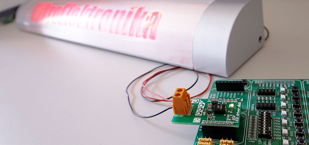
The MCP1662 device is a compact, space-efficient, fixed-frequency, non-synchronous step-up converter optimized to drive LED strings with a constant current from a two- or three-cell alkaline or lithium Energizer®, or NiMH/NiCd, or one-cell Lithium-Ion or Li-Polymer batteries.
The device integrates a 36V, 800 mW low-side switch, which is protected by the 1.3A cycle-by-cycle inductor peak current limit operation.
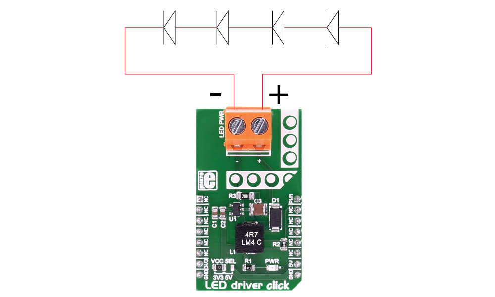
LED driver click has a power input and a PWM input, so the LED lights can be dimmed. It's a great choice for driving LED strips.
Type
LED Drivers
Applications
LED strings with a constant current from a two- or three-cell alkaline or lithium Energizer®, or NiMH/NiCd, or one-cell Lithium-Ion or Li-Polymer batteries
On-board modules
MCP1662 High-Voltage Step-Up LED Driver
Key Features
Open Load Protection, Overtemperature Protection, Input Voltage Range: 2.4V to 5.5V
Interface
PWM
Feature
No ClickID
Compatibility
mikroBUS™
Click board size
M (42.9 x 25.4 mm)
Input Voltage
3.3V or 5V
This table shows how the pinout on LED driver click corresponds to the pinout on the mikroBUS™ socket (the latter shown in the two middle columns).
| Notes | Pin | Pin | Notes | ||||
|---|---|---|---|---|---|---|---|
| NC | 1 | AN | PWM | 16 | PWM | PWM input | |
| NC | 2 | RST | INT | 15 | NC | ||
| NC | 3 | CS | TX | 14 | NC | ||
| NC | 4 | SCK | RX | 13 | NC | ||
| NC | 5 | MISO | SCL | 12 | NC | ||
| NC | 6 | MOSI | SDA | 11 | NC | ||
| Power supply | +3.3V | 7 | 3.3V | 5V | 10 | +5V | Power supply |
| Ground | GND | 8 | GND | GND | 9 | GND | Ground |
| Description | Min | Typ | Max | Unit |
|---|---|---|---|---|
| Supply Voltage | 2.4 | 5.5 | V | |
| Max Out Voltage | 32 | V | ||
| Max Out Current 4.2V Vin 8 LEDs | 100 | mA | ||
| Max Out Current 3.3V Vin 4 LEDs | 125 | mA | ||
| Max Out Current 5.0V Vin 4 LEDs | 200 | mA |
Code examples for LED driver click, written for MikroElektronika hardware and compilers are available on Libstock.
The following code snippet shows the LED driver click example, which initializes ADC and PWM and sets the PWM output depending on the potentiometer analog input.
01 void systemInit()
02 {
03     TRISC = 0;                          // designate PORTC pins as output
04     LATC  = 0;                          // set PORTC to 0
05     PWM2_Init( 5000 );                  // Initialize PWM2 module at 5KHz
06 }
07
08 void main()
09 {
10     systemInit();
11     currentDuty  = 0;
12     PWM2_Start();
13     PWM2_Set_Duty(currentDuty);
14
15    while ( 1 )                         // Playing with Potentiometer P1 you can control current PWM duty cycle
16     {
17         currentDuty = ADC_Read(1) & 0x0000FFFF;         // Read 10 - bit ADC value and set newly acquired 8 - bit PWM duty
18         currentDuty = currentDuty / 4;
19         PWM2_Set_Duty(currentDuty );          // Set newly acquired duty
20     }
21
22 }
NOTE: Please be advised that any peripheral devices or accessories shown connected to the Click board™ are not included in the package. Check their availability in our shop or in the YMAN section below.

$889.00

$95.00

$549.00

$299.00

$29.00

$29.00

$3.30

$3.60

$119.00

$449.00

$349.00

$349.00

$349.00

$299.00

$269.00

$249.00

$209.00
