


OFF
GO LOCAL
| Company | Stock | Price |
|---|---|---|


MIKROE-4268
19 g
Status:
LED Driver 8 Click is a compact add-on board optimized for dimming and blinking 32 mA RGBA LEDs. This board features the PCA9957HNMP, 24-channel SPI-compatible constant current LED driver from NXP Semiconductors. It has 24 LED output channels with a programmable group dimming/blinking mixed with individual LED brightness, and programmable LED output delay to reduce EMI and surge currents. It also possesses gradation control for all channels where all 24 constant current output channels can sink up to 32 mA, and tolerate up to 5.5 V in its OFF state. As the name itself says, this Click board™ next to driving RGBA LEDs can be used in the purpose of LED Status signalization, in LED displays, LED backlight, keypad backlights for cellular phones, or handheld devices, and many more.
LED Driver 8 Click is supported by a mikroSDK compliant library, which includes functions that simplify software development. This Click board™ comes as a fully tested product, ready to be used on a system equipped with the mikroBUS™ socket.
This product is no longer in stock
Availability date:
OFF
| Company | Stock | Price |
|---|---|---|
LED Driver 8 Click is based on the PCA9957, a daisy-chain SPI compatible 4-wire serial bus controlled 24-channel constant current LED driver optimized for dimming and blinking 32 mA RGBA LEDs from NXP Semiconductors. The PCA9957 has 24 internal 8-bit DACs with an operating frequency of 31.25 kHz and a duty cycle from 0% to 100% used to adjust brightness levels for each LED current source. Each LED output is programmable and can be turned off, on (with no PWM control), set at its individual PWM controller value, or both individual and group PWM controller values. Its output peak current is adjustable with an 8-bit linear DAC from 125 μA to 31.875 mA because of the R4 resistor of 2kΩ connected to the REXT pin.
Gradation control for all current sources is achieved through serial interface and allows the user to ramp current automatically without any help from the MCU. It has two operation modes for each group: Single-Shot Mode (output pattern once) and Continuous Mode (output pattern repeat). Each channel can be set to either Gradation Mode or Normal Mode and assigned to any one of six gradation control groups. These groups have four independent registers to control ramp-up and ramp-down rate, step time, hold ON/OFF time, and final hold ON output current.
The LED Driver 8 Click communicates with MCU through a daisy-chain SPI compatible 4-wire serial interface with a clock frequency up to 10 MHz. The input labeled as OE routed to the PWM pin on the mikroBUS™ blinks all the LED outputs and can be used to externally PWM the outputs, which is useful when multiple devices need to be dimmed or blinked together without using software control. The PCA9957 also has a short load and overtemperature detection circuitry, thermal shutdown feature which protects the device when the internal junction temperature exceeds the factory-defined limit, and a Reset function routed to the RST pin on the mikroBUS™ which is activated by sending an active low input on this pin with a minimum pulse width of 2.5μs.
This Click board™ is designed to be operated with both 3.3V and 5V logic voltage levels that can be selected via VCC SEL jumper. This allows for both 3.3V and 5V capable MCUs to use the SPI communication lines properly.
Type
LED Drivers
Applications
Can be used in the purpose of LED Status signalization, in LED displays, LED backlight, keypad backlights for cellular phones, or handheld devices, and many more.
On-board modules
LED Driver 8 Click is based on the PCA9957, a daisy-chain SPI compatible 4-wire serial bus controlled 24-channel constant current LED driver optimized for dimming and blinking 32 mA RGBA LEDs from NXP Semiconductors.
Key Features
Low power consumption, programmable LED drivers channels, gradation control for all channels, low standby current, no glitch on LED outputs on Power-Up, and more.
Interface
SPI
Feature
No ClickID
Compatibility
mikroBUS™
Click board size
M (42.9 x 25.4 mm)
Input Voltage
3.3V or 5V
This table shows how the pinout on LED Driver 8 Click corresponds to the pinout on the mikroBUS™ socket (the latter shown in the two middle columns).
| Notes | Pin | Pin | Notes | ||||
|---|---|---|---|---|---|---|---|
| NC | 1 | AN | PWM | 16 | OE | Output Enable | |
| Reset | RST | 2 | RST | INT | 15 | NC | |
| SPI Chip Select | CS | 3 | CS | RX | 14 | NC | |
| SPI Clock | SCK | 4 | SCK | TX | 13 | NC | |
| SPI Data OUT | SDO | 5 | MISO | SCL | 12 | NC | |
| SPI Data IN | SDI | 6 | MOSI | SDA | 11 | NC | |
| Power Supply | 3.3V | 7 | 3.3V | 5V | 10 | 5V | Power Supply |
| Ground | GND | 8 | GND | GND | 9 | GND | Ground |
| Label | Name | Default | Description |
|---|---|---|---|
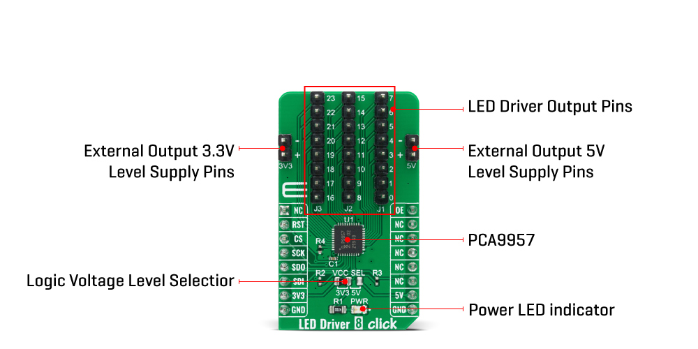
| LD1 | PWR | - | Power LED Indicator |
| JP1 | VCC SEL | left | Power Supply Voltage Selection 3V3/5V: Left position 3V3, Right position 5V |
| J1-J3 | - | - | LED Driver Output Header |
| J4 | - | - | External Output 3.3V Level Supply Header |
| J5 | - | - | External Output 5V Level Supply Header |
| Description | Min | Typ | Max | Unit |
|---|---|---|---|---|
| Supply Voltage | -0.5 | - | 6 | V |
| Maximum Output Current on LED pins | - | - | 40 | mA |
| SPI Clock Frequency | - | - | 10 | MHz |
| Operating Temperature Range | -40 | - | +85 | °C |
We provide a library for the Led Driver 8 Click on our LibStock page, as well as a demo application (example), developed using MikroElektronika compilers. The demo can run on all the main MikroElektronika development boards.
Library Description
The library contains a basic functions for using LED Driver 8 click.
Key functions:
void leddriver8_set_mode_register( uint8_t mode_1, uint8_t mode_2 ) - Function for set mode registersvoid leddriver8_set_output_gain ( uint8_t num_led, uint8_t value ) - Functions for set output gainvoid leddriver8_set_brightness ( uint8_t num_led, uint8_t value ) - Functions for set BrightnessExamples description
The application is composed of three sections :
void application_task ( )
{
    uint8_t cnt;
    for( cnt = 0; cnt < 0xFF; cnt++ )
    {
        leddriver8_set_brightness( LEDDRIVER8_BRIGHTNESS_ALL_LED, cnt );
        Delay_ms( 15 );
    }

    for( cnt = 0; cnt < 5; cnt++ )
    {
       leddriver8_set_brightness( LEDDRIVER8_LED_0, 200 );
       Delay_ms( 1000 );
       leddriver8_set_brightness( LEDDRIVER8_LED_0, 0 );
       Delay_ms( 1000 );
    }
}
The full application code, and ready to use projects can be found on our LibStock page.
Other mikroE Libraries used in the example:
Additional notes and informations
Depending on the development board you are using, you may need USB UART click, USB UART 2 click or RS232 click to connect to your PC, for development systems with no UART to USB interface available on the board. The terminal available in all MikroElektronika compilers, or any other terminal application of your choice, can be used to read the message.
This Click board™ is supported with mikroSDK - MikroElektronika Software Development Kit. To ensure proper operation of mikroSDK compliant Click board™ demo applications, mikroSDK should be downloaded from the LibStock and installed for the compiler you are using.
For more information about mikroSDK, visit the official page.
NOTE: Please be advised that any peripheral devices or accessories shown connected to the Click board™ are not included in the package. Check their availability in our shop or in the YMAN section below.

$889.00

$95.00

$549.00

$299.00

$29.00

$29.00

$6.59

$3.60

$119.00

$449.00

$349.00

$349.00

$349.00

$299.00

$269.00

$249.00

$209.00
