


OFF
GO LOCAL
| Company | Stock | Price |
|---|---|---|


MIKROE-4335
21 g
Status:
eFuse 2 Click is a compact add-on board that contains an integrated FET hot-swap device. This board features the TPS259631, a highly integrated circuit protection and power management solution from Texas Instruments. It provides multiple protection modes against overloads, short circuits, voltage surges, and excessive inrush current. Also, it is possible to get an accurate sense of the output load current by measuring the voltage drop across digital rheostat that can set the output current limit level. The device also uses an in-built thermal shutdown mechanism to protect itself during these fault events. This Click board™ is typically used for hot-swapping and power rail protection applications.
eFuse 2 Click is supported by a mikroSDK compliant library, which includes functions that simplify software development. This Click board™ comes as a fully tested product, ready to be used on a system equipped with the mikroBUS™ socket.
This product is no longer in stock
Availability date:
OFF
| Company | Stock | Price |
|---|---|---|
eFuse 2 Click is based on the TPS259631, an integrated eFuse device that is used to manage load voltage and load current from Texas Instruments. The TPS259631 provides various factory-programmed settings and user manageable settings, which allow device configuration for handling different transient and steady-state supply and load fault conditions, thereby protecting the input supply and the downstream circuits connected to the device. The device also uses an in-built thermal shutdown mechanism to shield itself during these fault events.
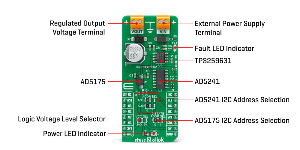
This Click board™ provides a simple solution for current limiting, inrush current control, and supervision of power rails for a wide range of applications operating from 2.7 V to 19 V external power supply and delivering up to 2A. Besides, the eFuse 2 Click board™ monitors the input supply the entire time and comes up with a user-adjustable UVLO and OVLO ... mechanism through an I2C compatible digital potentiometer, the AD5241 from Analog Devices, to ensure that the load is powered up only when the voltage is at a sufficient level.
It is also possible to get an accurate sense of the output load current by measuring the voltage drop across the current limit resistor. By replacing the resistor with a digital rheostat, you can easily program the current limit as performed on this Click board™. For this purpose, the AD5175 single-channel 1024-position digital rheostat from Analog Devices that communicate with the MCU through the I2C serial interface is used to program the current limit. The TPS259631 regulates the current to the set current limit value within the nominal overcurrent response time and exits current limiting when the load current falls below the current limit value.
The eFuse 2 Click board™ allows the choice of the least significant bit (LSB) of the I2C slave addresses for both AD5241 and AD5175. This can be performed by positioning the SMD jumper labeled as ADDR SEL to its appropriate position. Additional functionality such as hardware reset for AD5175 and fault indication interrupt is provided and routed at RST and INT pins of the mikroBUS™ socket labeled as RST and FLT. This open-drain fault output is associated with a red color LED indicator, marked as the FLT that will be pulled low when a fault is detected.
This Click board™ is designed to be operated with both 3.3V and 5V logic voltage levels that can be selected via VCC SEL jumper. This allows for both 3.3V and 5V capable MCUs to use the I2C communication lines properly. However, this Click board™ comes equipped with a library that contains easy to use functions and an example code that can be used as a reference for further development.
Type
Power Switch
Applications
Can be used for hot-swapping and power rail protection applications.
On-board modules
eFuse 2 Click is based on the TPS259631, an integrated eFuse device that is used to manage load voltage and load current from Texas Instruments.
Key Features
Adjustable current limit with load current monitor, overtemperature protection, fault indication, overvoltage protection, and adjustable undervoltage lockout, wide input voltage range, and more.
Interface
I2C
Feature
No ClickID
Compatibility
mikroBUS™
Click board size
L (57.15 x 25.4 mm)
Input Voltage
3.3V or 5V
This table shows how the pinout on 9DOF 2 Click corresponds to the pinout on the mikroBUS™ socket (the latter shown in the two middle columns).
| Notes | Pin | Pin | Notes | ||||
|---|---|---|---|---|---|---|---|
| NC | 1 | AN | PWM | 16 | NC | ||
| Reset | RST | 2 | RST | INT | 15 | FLT | Fault Indication |
| NC | 3 | CS | RX | 14 | NC | ||
| NC | 4 | SCK | TX | 13 | NC | ||
| NC | 5 | MISO | SCL | 12 | SCL | I2C Clock | |
| NC | 6 | MOSI | SDA | 11 | SDA | I2C Data | |
| Power Supply | 3.3V | 7 | 3.3V | 5V | 10 | 5V | Power Supply |
| Ground | GND | 8 | GND | GND | 9 | GND | Ground |
| Label | Name | Default | Description |
|---|---|---|---|
| LD1 | PWR | - | Power LED Indicator |
| LD2 | FLT | - | Fault LED Indicator |
| JP1 | VCC SEL | Left | Power Supply Voltage Selection 3V3/5V: Left position 3V3, Right position 5V |
| JP2-JP3 | ADDR SEL | Left | AD5241 I2C Address Selection: Left position 0, Right position 1 |
| JP4 | 3 STATE ADDR SEL | Left | AD5175 I2C Address Selection: Left position 0, Right position 1 |
| Description | Min | Typ | Max | Unit |
|---|---|---|---|---|
| Supply Voltage | 2.7 | - | 19 | V |
| Current Limit | 0.13 | - | 2 | A |
| I2C Clock Frequency | - | - | 400 | kHz |
| Operating Temperature Range | -40 | - | +125 | °C |
We provide a library for the eFuse 2 Click on our LibStock page, as well as a demo application (example), developed using MikroElektronika compilers. The demo can run on all the main MikroElektronika development boards.
Library Description
The library covers all the necessary functions to control eFuse 2 Click board™. Library performs a standard I2C interface communication.
Key functions:
float *min_voltage, float *max_voltage ) - Set operating voltage function.void efuse2_set_operating_current ( float current ) - Set operating current function.void efuse2_operating_mode ( uint8_t mode ) - Set operating mode function.Examples description
The application is composed of three sections :
void application_task ( )
{
    if ( efuse2_get_fault( ) == EFUSE2_FAULT )
    {
        efuse2_operating_mode( EFUSE2_AD5175_SHUTDOWN_MODE );
        Delay_ms( 1000 );

        mikrobus_logWrite( "        Shutdown Mode        ", _LOG_LINE );
        mikrobus_logWrite( "-----------------------------", _LOG_LINE );
        for ( ; ; );
    }

    FloatToStr( op_voltage, log_text );
    mikrobus_logWrite( " Oper. Voltage : ", _LOG_TEXT );
    mikrobus_logWrite( log_text, _LOG_TEXT );
    mikrobus_logWrite( " V", _LOG_LINE );

    FloatToStr( min_voltage, log_text );
    mikrobus_logWrite( " Undervoltage  : ", _LOG_TEXT );
    mikrobus_logWrite( log_text, _LOG_TEXT );
    mikrobus_logWrite( " V", _LOG_LINE );

    FloatToStr( max_voltage, log_text );
    mikrobus_logWrite( " Overvoltage   : ", _LOG_TEXT );
    mikrobus_logWrite( log_text, _LOG_TEXT );
    mikrobus_logWrite( " V", _LOG_LINE );

    FloatToStr( op_current, log_text );
    mikrobus_logWrite( " Current Limit : ", _LOG_TEXT );
    mikrobus_logWrite( log_text, _LOG_TEXT );
    mikrobus_logWrite( " A", _LOG_LINE );
    mikrobus_logWrite( "-----------------------------", _LOG_LINE );
    Delay_ms( 2000 );
}
The full application code, and ready to use projects can be found on our LibStock page.
Other mikroE Libraries used in the example:
Additional notes and informations
Depending on the development board you are using, you may need USB UART click, USB UART 2 click or RS232 click to connect to your PC, for development systems with no UART to USB interface available on the board. The terminal available in all MikroElektronika compilers, or any other terminal application of your choice, can be used to read the message.
This Click board™ is supported with mikroSDK - MikroElektronika Software Development Kit. To ensure proper operation of mikroSDK compliant Click board™ demo applications, mikroSDK should be downloaded from the LibStock and installed for the compiler you are using.
For more information about mikroSDK, visit the official page.
NOTE: Please be advised that any peripheral devices or accessories shown connected to the Click board™ are not included in the package. Check their availability in our shop or in the YMAN section below.

$889.00

$95.00

$549.00

$299.00

$29.00

$29.00

$6.59

$3.60

$119.00

$449.00

$349.00

$349.00

$349.00

$299.00

$269.00

$249.00

$209.00
