


OFF
GO LOCAL
| Company | Stock | Price |
|---|---|---|


MIKROE-4352
22 g
Status:
Driver 2 Click is a compact add-on board that contains a gate driver with a level-shift technology with an additional Shutdown function. This board features the IR2104S, a high voltage, high-speed power MOSFET and IGBT driver with typical 0.21 A source and 0.36 A sink currents and independent high and low side referenced output channels from Infineon Technologies. It consists of a level shifter in combination with a power amplifier that accepts a low-power input compatible with standard CMOS or LSTTL outputs and produces a high-current drive input for the gate of a high-power transistor. This Click board™ is suitable for any application ranging from DC-DC power supply for high power density and efficiency up to a wide range of motor applications.
Driver 2 Click is supported by a mikroSDK compliant library, which includes functions that simplify software development. This Click board™ comes as a fully tested product, ready to be used on a system equipped with the mikroBUS™ socket.
This product is no longer in stock
Availability date:
OFF
| Company | Stock | Price |
|---|---|---|
Driver 2 Click is based on the IR2104S, a high-voltage, high-speed power MOSFET and IGBT driver with typical 0.21A source and 0.36A sink currents and independent high and low side referenced output channels from Infineon Technologies. A gate driver IR2104S represents a power amplifier that accepts a low-power input from a controller IC and produces a high-current drive input for the gate of a high-power transistor such as a power MOSFET. In essence, it consists of a level shifter in combination with an amplifier. It has many applications, ranging from the DC-DC power supply for high power density and efficiency up to a wide range of motor applications such as home appliances, industrial drives, DC brushed and brushless motors, and more.
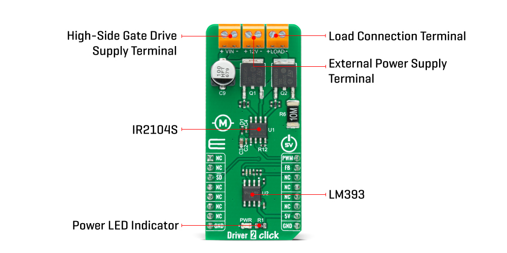
This Click board™ has a logic input compatible with standard CMOS or LSTTL outputs, down to 3.3V logic, and features the additional Shutdown function. The output drivers feature a high pulse current buffer stage designed for minimum driver cross-conduction. It also possesses precision voltage comparator the LM393, with an input offset voltage specifications as low as 2.0 mV built to permit a common-mode range–to–ground level with single supply operation from STMicroelectronics. In combination with the INT pin, with the help of this comparator, we can get feedback in case of exceeding the maximum current value on the LOAD terminal (over-current detection).
Driver 2 Click operates with the PWM signal that drives the input IN pin of the IR2104S and communicates with MCU with two other pins routed on the INT and CS pins of the mikroBUS™ socket labeled as FB and SD. This Click board™ possesses 3 connectors, where one of them represents an external power supply labeled as VIN in the range from 12 to 45V. The next one is the gate driver power supply terminal with a fixed voltage value of 12V, and the last terminal labeled as LOAD is a terminal that can supply the load with maximum current up to 10A.
Additional functionality, as mentioned before, are two pins routed on the CS and INT pins of the mikroBUS™ socket. A signal on the CS pin labeled as SD represents Shutdown function able to turns off both channels of the IR2104S, whiles another pin, INT, marked as the FB is an indication, more accurately an interrupt, to the MCU if the maximum value of the output current is exceeded.
This Click board™ is designed to be operated only with a 5V logic voltage level. A proper logic voltage level conversion should be performed before the Click board™ is used with MCUs with different logic levels. However, the Click board™ comes equipped with a library that contains easy to use functions and an example code that can be used as a reference for further development.
Type
Brushed
Applications
Can be used for many applications, ranging from the DC-DC power supply for high power density and efficiency up to a wide range of motor applications such as home appliances, industrial drives, DC brushed and brushless motors, and more.
On-board modules
Driver 2 Click is based on the IR2104, a high-voltage, high-speed power MOSFET and IGBT driver with typical 0.21A source and 0.36A sink currents and independent high and low side referenced output channels from Infineon Technologies.
Key Features
Low power consumption, high precission
Interface
GPIO,PWM
Feature
No ClickID
Compatibility
mikroBUS™
Click board size
L (57.15 x 25.4 mm)
Input Voltage
5V,External
This table shows how the pinout on Driver 2 Click corresponds to the pinout on the mikroBUS™ socket (the latter shown in the two middle columns).
| Notes | Pin | Pin | Notes | ||||
|---|---|---|---|---|---|---|---|
| NC | 1 | AN | PWM | 16 | PWM | PWM Signal | |
| NC | 2 | RST | INT | 15 | FB | Feedback | |
| Shutdown | SD | 3 | CS | RX | 14 | NC | |
| NC | 4 | SCK | TX | 13 | NC | ||
| NC | 5 | MISO | SCL | 12 | NC | ||
| NC | 6 | MOSI | SDA | 11 | NC | ||
| NC | 7 | 3.3V | 5V | 10 | 5V | Power Supply | |
| Ground | GND | 8 | GND | GND | 9 | GND | Ground |
| Label | Name | Default | Description |
|---|---|---|---|
| LD1 | PWR | - | Power LED Indicator |
| Description | Min | Typ | Max | Unit |
|---|---|---|---|---|
| Supply Voltage | 10 | 12 | 20 | V |
| High-Side Gate Drive Supply Voltage (VIN) | 12 | - | 45 | V |
| Maximum Output Current | - | - | 10 | A |
| Output Current (Sink) | - | 0.36 | - | A |
| Output Current (Source) | - | 0.21 | - | V |
| Operating Temperature Range | -40 | - | +125 | °C |
We provide a library for the Driver 2 Click on our LibStock page, as well as a demo application (example), developed using MikroElektronika compilers. The demo can run on all the main MikroElektronika development boards.
Library Description
The library contains a basic functions for using Driver 2 click.
Key functions:
void driver2_set_sd_pin ( uint8_t state ) - Set SD pinvoid driver2_set_pwm_pin ( uint8_t state ) - Set PWM pinuint8_t driver2_get_fb_pin ( void ) - Get FB pinExamples description
The application is composed of three sections :
void application_task ( )
{
    for ( duty_cycle = 0; duty_cycle < pwm_period; duty_cycle += 25 )
    {
        driver2_pwm_set_duty( duty_cycle );
        Delay_ms( 100 );
    }
    for ( duty_cycle = pwm_period; duty_cycle <= 0; duty_cycle -= 25 )
    {
        driver2_pwm_set_duty( duty_cycle );
        Delay_ms( 100 );
    }
}
The full application code, and ready to use projects can be found on our LibStock page.
Other mikroE Libraries used in the example:
Additional notes and informations
Depending on the development board you are using, you may need USB UART click, USB UART 2 click or RS232 click to connect to your PC, for development systems with no UART to USB interface available on the board. The terminal available in all MikroElektronika compilers, or any other terminal application of your choice, can be used to read the message.
This Click board™ is supported with mikroSDK - MikroElektronika Software Development Kit. To ensure proper operation of mikroSDK compliant Click board™ demo applications, mikroSDK should be downloaded from the LibStock and installed for the compiler you are using.
For more information about mikroSDK, visit the official page.
NOTE: Please be advised that any peripheral devices or accessories shown connected to the Click board™ are not included in the package. Check their availability in our shop or in the YMAN section below.

$889.00

$95.00

$549.00

$299.00

$29.00

$29.00

$3.30

$3.60

$119.00

$449.00

$349.00

$349.00

$349.00

$299.00

$269.00

$249.00

$209.00
