


OFF
GO LOCAL
| Company | Stock | Price |
|---|---|---|


MIKROE-4414
17 g
Status:
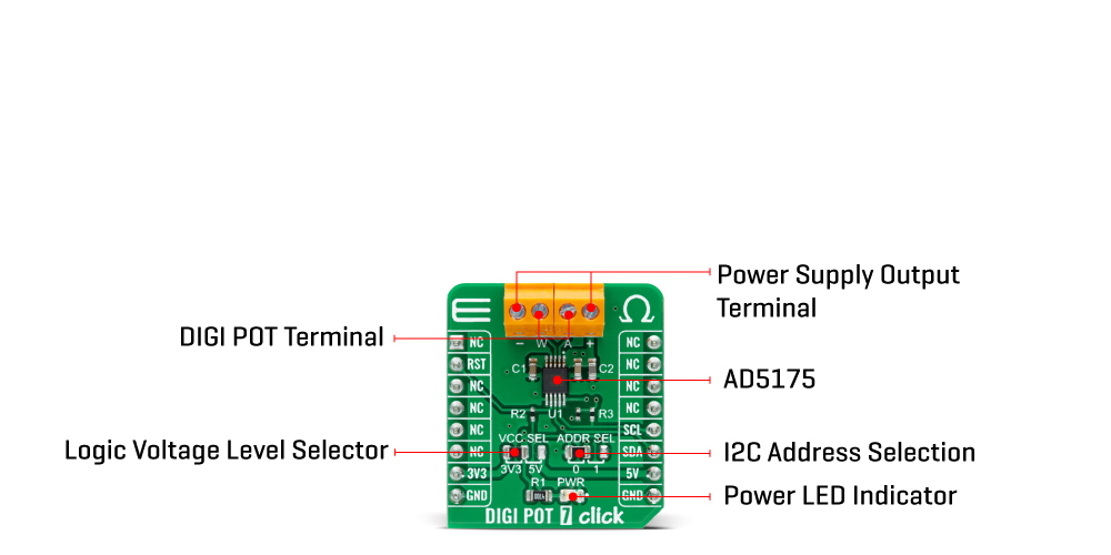
DIGI POT 7 Click is a compact add-on board used as a digitally controlled potentiometer. This board features the AD5175, a single-channel 1024-position digital rheostat with less than ±1% end-to-end resistor tolerance error and 50-time programmable wiper memory from Analog Devices. This I2C configurable IC is designed to operate as a variable resistor for analog signals, within the voltage range of single-supply operation at 2.7 V to 5.5 V. Unlimited adjustments are allowed before programming the resistance value into the programmable memory. This Click board™ can be used as a mechanical rheostat replacements, in voltage to current conversions, for gain and offset adjustment, and many more applications.
DIGI POT 7 Click is supported by a mikroSDK compliant library, which includes functions that simplify software development. This Click board™ comes as a fully tested product, ready to be used on a system equipped with the mikroBUS™ socket.
This product is no longer in stock
Availability date:
OFF
| Company | Stock | Price |
|---|---|---|
DIGI POT 7 Click is based on the AD5175, a single-channel 1024-position digital rheostat, with less than ±1% end-to-end resistor tolerance error and a 50-time programmable (50-TP) wiper memory from Analog Devices. It possesses one register named RDAC that determines the resistor Wiper position and acts as a scratchpad register allowing unlimited resistance settings. The RDAC register can be programmed with any position-set using the serial interface. When a desirable Wiper position is found, this value can be stored in a 50-TP memory register. Besides, the Wiper position is always restored to that position for subsequent Power-Up.
The storing of 50-TP data takes approximately 350 ms, and during this time, the AD5175 is locked and doesn't acknowledge any new command preventing any changes from taking place. The nominal resistance between terminal W and terminal A is 10kΩ with 1024-tap points accessed by the Wiper terminal, while in the Zero-Scale condition, a total Wiper resistance of 120Ω is present. The 10-bit data inside the RDAC register is decoded to select one of the 1024 possible Wiper settings.
The AD5175 also provides the possibility of the Shutdown feature by executing the software shutdown command. This feature places the RDAC register in a Zero-Power-Consumption state where terminal A is disconnected from the Wiper terminal. The AD5175 can be taken out of Shutdown Mode by executing Software Shutdown Command or performing the Hardware Reset feature.
DIGI POT 7 click communicates with MCU using the standard I2C 2-Wire interface, with a clock frequency up to 100kHz in the Standard and 400kHz in the Fast Mode. Besides, also allows the choice of the least significant bit (LSB) of its I2C slave address by positioning the SMD jumper labeled as ADDR SEL to an appropriate position marked as 0 and 1. This Click board™ can be reset via software by calling the Reset command that loads the RDAC register with the contents of the most recently programmed 50-TP memory location. This register loads with mid-scale if no 50-TP memory location has been previously programmed. It also can be reset through the Hardware Reset pin, labeled as RST on the mikroBUS™ socket, by putting this pin in a logic low state.
This Click board™ is designed to operate with both 3.3V and 5V logic voltage levels selected via the VCC SEL jumper. It allows for both 3.3V and 5V capable MCUs to use the I2C communication lines properly. However, the Click board™ comes equipped with a library that contains functions and an example code that can be used, as a reference, for further development.
Type
Digital potentiometer
Applications
Can be used as mechanical rheostat replacements, in a voltage to current conversions, for gain and offset adjustment, and many more applications
On-board modules
AD5175 - a single-channel 1024-position digital rheostat, with less than ±1% end-to-end resistor tolerance error and a 50-time programmable (50-TP) wiper memory from Analog Devices.
Key Features
Low power consumption, high precission, 50-times programmable wiper memory, 10 kΩ nominal resistance, I2C compatible, and more.
Interface
I2C
Feature
No ClickID
Compatibility
mikroBUS™
Click board size
S (28.6 x 25.4 mm)
Input Voltage
3.3V or 5V
This table shows how the pinout on DIGI POT 7 Click corresponds to the pinout on the mikroBUS™ socket (the latter shown in the two middle columns).
| Notes | Pin | Pin | Notes | ||||
|---|---|---|---|---|---|---|---|
| NC | 1 | AN | PWM | 16 | NC | ||
| Reset | RST | 2 | RST | INT | 15 | NC | |
| NC | 3 | CS | RX | 14 | NC | ||
| NC | 4 | SCK | TX | 13 | NC | ||
| NC | 5 | MISO | SCL | 12 | SCL | I2C Clock | |
| NC | 6 | MOSI | SDA | 11 | SDA | I2C Data | |
| Power Supply | 3.3V | 7 | 3.3V | 5V | 10 | 5V | Power Supply |
| Ground | GND | 8 | GND | GND | 9 | GND | Ground |
| Label | Name | Default | Description |
|---|---|---|---|
| LD1 | PWR | - | Power LED Indicator |
| JP1 | VCC SEL | Left | Logic Level Voltage Selection 3V3/5V: Left position 3V3, Right position 5V |
| JP2 | ADDR SEL | Left | I2C Address Selection 0/1: Left position 0, Right position 1 |
| Description | Min | Typ | Max | Unit |
|---|---|---|---|---|
| Supply Voltage | 3.3 | - | 5 | V |
| Wiper Resistance | - | 35 | 70 | Ω |
| Resolution | 10 | - | - | bits |
| Operating Temperature Range | -40 | +25 | +125 | °C |
We provide a library for the DIGI POT 7 Click on our LibStock page, as well as a demo application (example), developed using MikroElektronika compilers. The demo can run on all the main MikroElektronika development boards.
Package can be downloaded/installed directly from NECTO Studio Package Manager(recommended way), downloaded from our LibStock™ or found on mikroE github account.
Library Description
The library covers all the necessary functions to control DIGI POT 7 Click board™. Library performs a standard I2C interface communication.
Key functions:
void digipot7_enable_write ( void ) - Enable write function.void digipot7_operating_mode ( uint8_t mode ) - Set operating mode function.DIGIPOT7_RETVAL_T digipot7_set_resistance ( uint16_t res_ohm ) - Set resistance function.Examples description
The application is composed of three sections :
void application_task ( )
{
    mikrobus_logWrite( " Set Resistance: 1.024 kOhm ", _LOG_LINE );
    mikrobus_logWrite( "----------------------------", _LOG_LINE );
    digipot7_set_resistance( 1024 );
    Delay_ms( 5000 );

    mikrobus_logWrite( " Set Resistance: 2.048 kOhm ", _LOG_LINE );
    mikrobus_logWrite( "----------------------------", _LOG_LINE );
    digipot7_set_resistance( 2048 );
    Delay_ms( 5000 );

    mikrobus_logWrite( " Set Resistance: 4.096 kOhm ", _LOG_LINE );
    mikrobus_logWrite( "----------------------------", _LOG_LINE );
    digipot7_set_resistance( 4096 );
    Delay_ms( 5000 );

    mikrobus_logWrite( " Set Resistance: 8.192 kOhm ", _LOG_LINE );
    mikrobus_logWrite( "----------------------------", _LOG_LINE );
    digipot7_set_resistance( 8192 );
    Delay_ms( 5000 );
}
The full application code, and ready to use projects can be found on our LibStock page.
Other Mikroe Libraries used in the example:
Additional notes and informations
Depending on the development board you are using, you may need USB UART click, USB UART 2 click or RS232 click to connect to your PC, for development systems with no UART to USB interface available on the board. The terminal available in all MikroElektronika compilers, or any other terminal application of your choice, can be used to read the message.
This Click board™ is supported with mikroSDK - MikroElektronika Software Development Kit. To ensure proper operation of mikroSDK compliant Click board™ demo applications, mikroSDK should be downloaded from the LibStock and installed for the compiler you are using.
For more information about mikroSDK, visit the official page.
NOTE: Please be advised that any peripheral devices or accessories shown connected to the Click board™ are not included in the package. Check their availability in our shop or in the YMAN section below.

$889.00

$95.00

$549.00

$299.00

$29.00

$29.00

$6.59

$3.60

$119.00

$449.00

$349.00

$349.00

$349.00

$299.00

$269.00

$249.00

$209.00
