


OFF
GO LOCAL
| Company | Stock | Price |
|---|---|---|


MIKROE-4332
18 g
Status:
DAC 9 Click is a compact add-on board that contains a fully-featured, highly accurate digital-to-analog converter. This board features the DAC80501, a 16-bit voltage-output digital-to-analog converter with precision internal reference from Texas Instruments. It supports both I2C and SPI serial interface and offers a linearity of < 1 LSB. It also includes a 2.5V internal reference, giving full-scale output voltage ranges of 1.25V, 2.5V, or 5V, incorporate a Power-On Reset function, consume a low current of 1mA, and include a Power-Down feature that reduces current consumption to typically 15μA at 5V. This Click board™ is suitable for applications such as offset and gain control, VCO tuning, programmable reference, and more.
DAC 9 Click is supported by a mikroSDK compliant library, which includes functions that simplify software development. This Click board™ comes as a fully tested product, ready to be used on a system equipped with the mikroBUS™ socket.
This product is no longer in stock
Availability date:
OFF
| Company | Stock | Price |
|---|---|---|
DAC 9 Click is based on the DAC80501, a single-channel, buffered, 16-bit resolution digital-to-analog converter from Texas Instruments. It includes a 2.5V, 5ppm/˚C internal reference, giving full-scale output voltage ranges of 1.25V, 2.5V, or 5V, and incorporates a Power-On Reset function. This function makes sure that the DAC80501 output powers up at zero scale or midscale and remains at that scale until a valid code is written to the device. High resolution and simple interface features make this Click board™ suitable for applications such as battery testers, communications equipment, factory automation and control, test and measurement, and more.
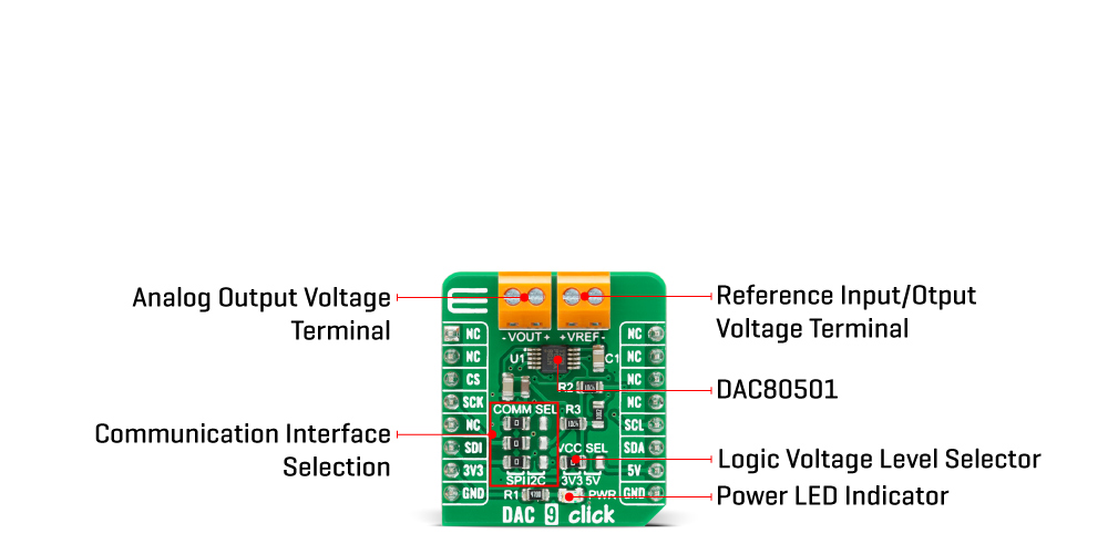
The output channel of the DAC80501, routed to the VOUT terminal, consists of a rail-to-rail ladder architecture with an output buffer amplifier that generates rail-to-rail voltages giving a maximum output range of 0V to VDD. The full-scale output range of the DAC output is determined by the reference voltage on the VREFIO pin, the reference divider setting, and the gain configuration for that channel set by the corresponding BUFF-GAIN bit. When the DAC80501 uses an internal reference, this voltage is also externally available at the VREF terminal and can sources up to 5mA. Besides, the user can bring the external reference voltage on this terminal in the case of the DAC80501 external reference configuration.
DAC 9 Click provides the possibility of using both I2C and SPI interfaces. The selection can be performed by positioning SMD jumpers labeled as COMM SEL to an appropriate position. Note that all jumpers must be placed to the same side, or else the Click board™ may become unresponsive. In SPI mode, the DAC80501 uses a 3-Wire SPI serial interface that operates at clock rates of up to 50MHz, while in I2C mode the DAC80501 can operate in Standard Mode (100 kbps), Fast Mode (400 kbps), and Fast-Plus Mode (1.0 Mbps).
This Click board™ is designed to be operated with both 3.3V and 5V logic voltage levels that can be selected via VCC SEL jumper. This allows for both 3.3V and 5V capable MCUs to use both the I2C and SPI communication lines properly. However, the Click board™ comes equipped with a library that contains easy to use functions and an example code that can be used as a reference for further development.
Type
DAC
Applications
Can be used for applications such as offset and gain control, VCO tuning, programmable reference, and more.
On-board modules
DAC 9 Click is based on the DAC80501, a 16-bit voltage-output digital-to-analog converter with precision internal reference from Texas Instruments.
Key Features
Low power consumption, low glitch energy, buffered output voltage range, internal/external voltage reference, selectable serial interface, high accuracy, and more.
Interface
I2C,SPI
Feature
No ClickID
Compatibility
mikroBUS™
Click board size
S (28.6 x 25.4 mm)
Input Voltage
3.3V or 5V
This table shows how the pinout on DAC 9 Click corresponds to the pinout on the mikroBUS™ socket (the latter shown in the two middle columns).
| Notes | Pin | Pin | Notes | ||||
|---|---|---|---|---|---|---|---|
| NC | 1 | AN | PWM | 16 | NC | ||
| NC | 2 | RST | INT | 15 | NC | ||
| SPI Chip Select | CS | 3 | CS | RX | 14 | NC | |
| SPI Clock | SCK | 4 | SCK | TX | 13 | NC | |
| NC | 5 | MISO | SCL | 12 | SCL | I2C Clock | |
| SPI Data IN | SDI | 6 | MOSI | SDA | 11 | SDA | I2C Data |
| Power Supply | 3.3V | 7 | 3.3V | 5V | 10 | 5V | Power Supply |
| Ground | GND | 8 | GND | GND | 9 | GND | Ground |
| Label | Name | Default | Description |
|---|---|---|---|
| LD1 | PWR | - | Power LED Indicator |
| JP1 | VCC SEL | Left | Power Supply Voltage Selection 3V3/5V: Left position 3V3, Right position 5V |
| JP2-JP4 | COMM SEL | Left | Communication Interface Selection: Left position SPI, Right position I2C |
| Description | Min | Typ | Max | Unit |
|---|---|---|---|---|
| Supply Voltage | -0.3 | - | 6 | V |
| Maximum VREF Supply Voltage (EXT) | -0.3 | - | VCC+0.3 | V |
| Maximum VOUT Output Voltage | -0.3 | - | VCC+0.3 | V |
| Resolution | - | 16 | - | bits |
| Operating Temperature Range | -40 | - | +125 | °C |
We provide a library for the DAC 9 Click on our LibStock page, as well as a demo application (example), developed using MikroElektronika compilers. The demo can run on all the main MikroElektronika development boards.
Library Description
The library covers all the necessary functions to control the DAC 9 Click board™. This library holds functions that can be used to write data to the device in order to set up the device or set output voltage. Read function can be used with I2C communication exclusively.
Key functions:
void dac9_soft_reset ( ); - The function is used to perform software reset.uint8_t dac9_set_gain ( uint16_t en_ref_div, uint16_t en_buff_gain ); - The function is used to set gain and internal voltage reference.uint8_t dac9_set_vout ( uint16_t vout_mv ); - The function is used set Vout ( mV ) by calculating input data and writing it to the DAC data register.Examples description
The application is composed of three sections :
void application_task ( )
{
    uint16_t n_cnt;

    for ( n_cnt = 0; n_cnt <= res; n_cnt += 500 )
    {
        WordToStr(n_cnt, log_txt );
        mikrobus_logWrite( "Output Voltage : ", _LOG_TEXT );
        Ltrim(log_txt);
        mikrobus_logWrite( log_txt, _LOG_TEXT );
        mikrobus_logWrite( "mV", _LOG_LINE );
        dac9_set_vout(  n_cnt );
        Delay_ms( 2000 );
    }
}
The full application code, and ready to use projects can be found on our LibStock page.
Other mikroE Libraries used in the example:
Additional notes and informations
Depending on the development board you are using, you may need USB UART click, USB UART 2 click or RS232 click to connect to your PC, for development systems with no UART to USB interface available on the board. The terminal available in all MikroElektronika compilers, or any other terminal application of your choice, can be used to read the message.
This Click board™ is supported with mikroSDK - MikroElektronika Software Development Kit. To ensure proper operation of mikroSDK compliant Click board™ demo applications, mikroSDK should be downloaded from the LibStock and installed for the compiler you are using.
For more information about mikroSDK, visit the official page.
NOTE: Please be advised that any peripheral devices or accessories shown connected to the Click board™ are not included in the package. Check their availability in our shop or in the YMAN section below.

$889.00

$95.00

$549.00

$299.00

$29.00

$29.00

$6.59

$3.60

$119.00

$349.00

$349.00

$299.00

$449.00

$349.00

$269.00

$249.00

$209.00
