


OFF
GO LOCAL
| Company | Stock | Price |
|---|---|---|


MIKROE-4062
20 g
Status:
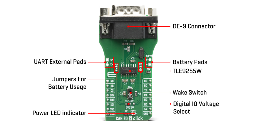
CAN FD 2 Click is a HS CAN transceiver add on board, suitable for evaluation of TLE9255W CAN network transceiver from Infineon. The transceiver itself drives the signals to the CAN bus and protects the microcontroller from interference generated within the CAN network. Based on the high symmetry of the CANH and CANL signals, the TLE9255W provides a very low level of electromagnetic emission within a wide frequency range, allowing the operation of the TLE9255W without a common mode choke in automotive and industrial applications.
CAN FD 2 Click board™ is supported by a mikroSDK compliant library, which includes functions that simplify software development. This Click board™ comes as a fully tested product, ready to be used on a system equipped with the mikroBUS™ socket.
This product is no longer in stock
Availability date:
OFF
| Company | Stock | Price |
|---|---|---|
CAN 2 FD Click features TLE9255W a CAN protocol controller a part of the Infineon standard HS CAN transceiver family and provides beside CAN partial networking functions also a CAN FD capability up to 5 MBit/s in HS CAN networks. Configured as a partial networking HS CAN transceiver the TLE9255W can drive and receive CAN FD messages. It can also be used to block the payload of CAN FD messages. This CAN FD tolerant feature allows the usage of microcontrollers in CAN FD networks, which are not CAN FD capable. The two non-low power modes (Normal-operating Mode and Receive-only Mode) and the two low power modes (Sleep Mode and Stand-by Mode) provide minimum current consumption based on the required functionality.
The SPI of TLE9255W controls the setup of the wake-up messages and the status message generated by the internal state machine. Most of the functions, including wake-up functions, INH output control, mode control, undervoltage control are configurable by the SPI. This allows a very flexible usage of the TLE9255W in different applications.
High speed CAN (HS CAN) is a serial bus system that connects microcontrollers, sensors and actuators for realtime control applications. ISO 11898-2 (2016) describes the use of the Controller Area Network (CAN) within road vehicles. According to the 7-layer OSI reference model the physical layer of a HS CAN bus system specifies the data transmission from one CAN node to all other available CAN nodes within the network. The CAN transceiver is part of the physical layer.
The HS CAN transceiver TLE9255W includes a receiver and a transmitter unit, allowing the transceiver to send data to the bus medium and monitoring the data from the bus medium at the same time. It converts the serial data stream, which is available on the transmit data input TxD, to a differential output signal on the CAN bus, provided by the CANH and CANL pins. The receiver stage of the TLE9255W monitors the data on the CAN bus and converts it to a serial, single-ended signal on the RxD output pin.
Given all the features its components offer, the CAN FD 2 Click is best used for HS CAN networks in automotive applications and HS CAN networks in industrial applications. The onboard SMD jumper labeled as the VIO SEL is used to select which voltage rail will be used as the logic voltage level. It offers voltage selection between 3.3V and 5V so that the click board™ can be interfaced with both the 3.3V and 5V capable MCUs. The two UART wires (RX and TX) can also be connected directly through two pins to UART External Pads on the left edge of the board. With R6 and R7 jumpers populated alows you to use click board with standard 12V battery connected on Battery Pads at right side of board.
Type
CAN,CAN FD
Applications
HS CAN networks in automotive applications and HS CAN networks in industrial applications
On-board modules
TLE9255W the HS CAN Transceiver with Partial Networking
Key Features
HS CAN standard data rates up to 1MBit/s, CAN FD data rates up to 5 Mbit/s, Very low electromagnetic emission, Fail safe features
Interface
SPI,UART
Feature
No ClickID
Compatibility
mikroBUS™
Click board size
L (57.15 x 25.4 mm)
Input Voltage
3.3V,5V
This table shows how the pinout on CAN FD 2 Click corresponds to the pinout on the mikroBUS™ socket (the latter shown in the two middle columns).
| Notes | Pin | Pin | Notes | ||||
|---|---|---|---|---|---|---|---|
| NC | 1 | AN | PWM | 16 | NC | ||
| NC | 2 | RST | INT | 15 | NC | ||
| SPI Chip Select | CS | 3 | CS | RX | 14 | TX | UART Transmit |
| SPI Clock | SCK | 4 | SCK | TX | 13 | RX | UART Receive |
| SPI Data OUT | SDO | 5 | MISO | SCL | 12 | NC | |
| SPI Data IN | SDI | 6 | MOSI | SDA | 11 | NC | |
| Power Supply | 3.3V | 7 | 3.3V | 5V | 10 | 5V | Power Supply |
| Ground | GND | 8 | GND | GND | 9 | GND | Ground |
| Label | Name | Default | Description |
|---|---|---|---|
| PWR | LED GREEN |
- | Power LED Indicator |
| SW | - | Down | Wake up switch sensitive on rising and falling edge |
| VIO SEL | - | Left | Logic voltage level selection: left position 3.3V, right position 5V |
| R6, R7 | - | NP | Jumpers for battery usage |
We provide a library for the CAN FD 2 Click on our LibStock page, as well as a demo application (example), developed using MikroElektronika compilers. The demo can run on all the main MikroElektronika development boards.
Library Description
The library covers all the necessary functions to control CAN FD 2 Click board. Library performs a standard UART communication.
Key functions:
void canfd2_set_mode ( uint8_t op_mode ) - Set operating mode function.void canfd2_read_block ( uint8_t *read_data, uint16_t length ) - Read block function.void canfd2_write_block ( uint8_t *write_data, uint16_t length ) - Write block function.Examples description
The application is composed of three sections :
void application_task ( )
{
    if ( app_mode == APP_MODE_RECEIVER )
    {
        // RECEIVER - UART polling
        char rd_msg[ 10 ] = { 0 };

        canfd2_read_block( &rd_msg[ 0 ], 8 );
        mikrobus_logWrite( rd_msg, _LOG_TEXT );
    }
    else
    {
        // TRANSMITER - TX each 3 sec

        canfd2_write_block( &demo_message_data[ 0 ], 8 );

        Delay_ms( 3000 );
    }
}
The full application code, and ready to use projects can be found on our LibStock page.
Other mikroE Libraries used in the example:
Additional notes and informations
Depending on the development board you are using, you may need USB UART click, USB UART 2 click or RS232 click to connect to your PC, for development systems with no UART to USB interface available on the board. The terminal available in all MikroElektronika compilers, or any other terminal application of your choice, can be used to read the message.
This Click board™ is supported with mikroSDK - MikroElektronika Software Development Kit. To ensure proper operation of mikroSDK compliant Click board™ demo applications, mikroSDK should be downloaded from the LibStock and installed for the compiler you are using.
For more information about mikroSDK, visit the official page.
NOTE: Please be advised that any peripheral devices or accessories shown connected to the Click board™ are not included in the package. Check their availability in our shop or in the YMAN section below.

$889.00

$95.00

$549.00

$299.00

$29.00

$29.00

$6.59

$3.60

$119.00

$449.00

$349.00

$349.00

$349.00

$299.00

$269.00

$249.00

$209.00
