Virtual COM ports are great for those projects when you need to establish communication with an embedded project, and have no UART peripheral on your board, besides the USB you programmed with. The USB Communications Device Class ( CDC ) can be used to make a USB device look like a RS-232 connection, enabling the user to communicate through USB, transmitting and receiving data through the serial port, to a terminal.
MikroElektronika has an easy-to-use library for USB devices that allows the user to make the USB device look as a Communications Device, Human Interface Device( HID ), or Mass Storage Device( MSD ). Today we will be talking about the CDC class when developing with a Virtual COM port.
USB Devices
USB can be used for many different types of devices such as audio, video, debugging, imaging or printers. The point of creating the Universal Serial Bus was to make a communication bus for all peripherals. USB is fast, reliable, supported by all operating systems, and requires no configuration or setup by the user. The idea for USB was plug n' play, that way USB could be used for any kind of peripheral on any computer and the user would not need to do any searching for drivers. Some things needed for developing a project with a USB device are a host that can support USB, a device driver on the host side along with your code on the projects' side, and you have to know what type of device class you are trying to emulate with your USB connection. On the host side, the computer must find a device driver for the type of device you are attempting to look like, as well as manage data flow, and sometimes provide power. On the device side, you must detect communications from the computer or other device, and be able to respond using standard protocols.

Virtual COM
The MikroE library uses USB protocols and disguises itself as a COM port to enable communication through the terminal using standard USART communication. The first step is disguising your USB connection using the USB_Device_CDClass. The next thing you must do is initialize the USB device library and setup an interrupt for when you have data received from the computer. Initializing the CDC class sends a device descriptor, configuration descriptor and a string descriptor. The descriptor file is used to tell the USB device what it is going to act like, and what it is going to look like, so that the computer sees it that way and treats it as such. After the computer receives this information, it recognizes the USB as a communication device and begins communication. Here is an example of the setup while attempting to use your USB as a virtual COM port.
#include// Buffer of 64 bytes char buffer[64]; // USB interrupt service routine void USB0Interrupt() iv IVT_INT_OTG_FS{ // Call library interrupt handler routine USBDev_IntHandler(); } void USBDev_CDCParamsChanged(){ } void USBDev_CDCDataReceived(uint16_t size){ // Prepare receive buffer USBDev_CDCSetReceiveBuffer(buffer); // Send back received packet USBDev_CDCSendData(buffer, size); } void main() { // Initialize CDC Class USBDev_CDCInit(); // Initialize USB device module USBDev_Init(); // Enable USB device interrupt NVIC_IntEnable(IVT_INT_OTG_FS); // Wait until device is configured (enumeration is successfully finished) while(USBDev_GetDeviceState() != _USB_DEV_STATE_CONFIGURED) ; // Set receive buffer where received data is stored USBDev_CDCSetReceiveBuffer(buffer); // Infinite loop while(1){ } }
This example simply receives any data from the computer and sends exactly what is received back to the terminal to be displayed. It uses the interrupt from the USB to receive and send data using the USB Device library. All you have to do is set a receiving buffer, and handle what you'd like to do with the received data in the USBDev_CDCDataReceived function.
To receive and transmit data on the computer side, simply use a program like PuTTY to interface with serial ports. The baud rate of the virtual COM port is auto-baud, so the baud does not need to be set and can be set to any normal baud rate, for example 9600.
Communication Device Class
The Communication Device Class (CDC) can be used in many different ways. For all the specifications on the many different ways you can use this class you can visit usb.org. CDC has many different ways of being initialized, but in the case of MikroElektronikas' library for virtual COM ports, we use 3 specific descriptors for initialization. One descriptor that is very important is called the USB_CDC_cfg_descriptor, which contains the configuration descriptor, interface descriptors, and endpoint descriptors for all of the interfaces. Here is an example of this descriptor:
const uint8_t USB_CDC_cfg_descriptor[_USB_CDC_CONFIG_DESC_SIZ] = {

    // Configuration Descriptor
    0x09,   //  bLength: Configuration Descriptor size
    0x02,   //  bDescriptorType: Configuration
    _USB_CDC_CONFIG_DESC_SIZ,       //  wTotalLength: number of returned bytes
    _USB_CDC_CONFIG_DESC_SIZ >> 8,
    0x02,   //  bNumInterfaces: 2 interfaces
    0x01,   //  bConfigurationValue: Configuration value
    0x00,   //  iConfiguration: Index of string descriptor describing the configuration
    0xC0,   //  bmAttributes: self powered
    0x32,   //  bMaxPower: 100 mA

    // Interface Descriptor
    0x09,   //  bLength: Interface Descriptor size
    _USB_DEV_DESCRIPTOR_TYPE_INTERFACE,  //  bDescriptorType: Interface
    0x00,   //  bInterfaceNumber: Number of Interface
    0x00,   //  bAlternateSetting: Alternate setting
    0x01,   //  bNumEndpoints: One endpoint used
    0x02,   //  bInterfaceClass: Communication Interface Class
    0x02,   //  bInterfaceSubClass: Abstract Control Model
    0x01,   //  bInterfaceProtocol: AT commands
    0x00,   //  iInterface: string descriptor index

    // Header Functional Descriptor
    0x05,   //  bLength: Descriptor size
    0x24,   //  bDescriptorType: CS_INTERFACE
    0x00,   //  bDescriptorSubtype: Header Functional Descriptor
    0x10,   //  bcdCDC: specification release number
    0x01,

    // Call Management Functional Descriptor
    0x05,   //  bFunctionLength: Descriptor size
    0x24,   //  bDescriptorType: CS_INTERFACE
    0x01,   //  bDescriptorSubtype: Call Management Functional descriptor
    0x00,   //  bmCapabilities: Device does not handle call management itself
    0x01,   //  bDataInterface: 1

    // Abstract Control Management Functional Descriptor
    0x04,   //  bFunctionLength: Descriptor size
    0x24,   //  bDescriptorType: CS_INTERFACE
    0x02,   //  bDescriptorSubtype: Abstract Control Management descriptor
    0x02,   //  bmCapabilities:  Device supports the request combination of
            //  Set_Line_Coding, Set_Control_Line_State,
            //  Get_Line_Coding, and the notification Serial_State

    // Union Functional Descriptor
    0x05,   //  bFunctionLength: Descriptor size
    0x24,   //  bDescriptorType: CS_INTERFACE
    0x06,   //  bDescriptorSubtype: Union functional descriptor
    0x00,   //  bMasterInterface: Communication class interface
    0x01,   //  bSlaveInterface0: Data Class Interface

    // Interrupt IN Endpoint Descriptor
    0x07,   //  bLength: Endpoint Descriptor size
    _USB_DEV_DESCRIPTOR_TYPE_ENDPOINT,   //  bDescriptorType: Endpoint
    0x80 | _USB_CDC_INT_EP_IN,           //  bEndpointAddress
    0x03,   //  bmAttributes: Interrupt
    0x08,   //  wMaxPacketSize
    0x00,
    0xFF,   //  bInterval

    // Data class interface descriptor
    0x09,   //  bLength: Endpoint Descriptor size
    _USB_DEV_DESCRIPTOR_TYPE_INTERFACE,  //  bDescriptorType:
    0x01,   //  bInterfaceNumber: Number of Interface
    0x00,   //  bAlternateSetting: Alternate setting
    0x02,   //  bNumEndpoints: Two endpoints used
    0x0A,   //  bInterfaceClass: CDC
    0x00,   //  bInterfaceSubClass
    0x00,   //  bInterfaceProtocol
    0x00,   //  iInterface
deo, debugging, imaging or printers. The point of creating the Universal Serial Bus was to make a communication bus for all peripherals. USB is fast, reliable, supported by all operating systems, and requires no configuration or setup by the user. The idea for USB was plug n' play, that way USB could be used for any kind of peripheral on any computer and the user would not need to do any searching for drivers. Some things needed for developing a project with a USB device are a host that can support USB, a device driver on the host side along with your code on the projects' side, and you have to know what type of device class you are trying to emulate with your USB connection. On the host side, the computer must find a device driver for the type of device you are emulating, as well as manage data flow, and sometimes provide power. Your device must detect communications from the computer or other device, and be able to respond using standard protocols.


    // Bulk OUT Endpoint Descriptor
    0x07,   //  bLength: Endpoint Descriptor size
    _USB_DEV_DESCRIPTOR_TYPE_ENDPOINT,   //  bDescriptorType: Endpoint
    _USB_CDC_BULK_EP_OUT,                //  bEndpointAddress
    0x02,   //  bmAttributes: Bulk
    64,     //  wMaxPacketSize
    0x00,
    0x00,   //  bInterval: ignore for Bulk transfer

    // Bulk IN Endpoint Descriptor
    0x07,   //  bLength: Endpoint Descriptor size
    _USB_DEV_DESCRIPTOR_TYPE_ENDPOINT,   //  bDescriptorType: Endpoint
    0x80 | _USB_CDC_BULK_EP_IN,          //  bEndpointAddress
    0x02,   //  bmAttributes: Bulk
    64,     //  wMaxPacketSize
    0x00,
    0x00    //  bInterval
};
How To Use
When using the VCP library it is very easy to establish a disguise for your USB and initialize communication. There are 2 things that you must have:
- interrupt handler to call the USBDev_IntHandler()
- a function used to set the receiving buffer.
The library is then controlled by the interrupt that is waiting for the USB interrupt to be triggered that represent the data from the computer into the receive buffer for the application. After programming your board the library will start working and the PC connected will recognize the USB as a Communications Device and can begin communication. Simply open up your terminal application, like PuTTY. Find out what serial port your USB device is on by opening up the device manage in windows and looking under Ports (COM & LPT). Your device should come up as USB Serial Port followed by what COM number it is. Place that in the text box in PuTTY and set the baud rate to a normal baud rate like 9600. Click Open at the bottom right of PuTTY and begin typing. It might look like you are just typing into the terminal, but actually that is what is being sent back to the terminal from your device.
Pretty cool huh? And it was pretty painless too.
Summary
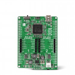
Virtual COM ports can be very useful in those rare cases where your project just doesn't have a port for UART communication, and you have to improvise and trick the computer into thinking that you do. There are many different ways to use the USB_Device library to fit your projects needs, and have been made very easy by the MikroE library. Go try this out on our Clicker 2 with the STM32, it works great!
References
USB Class Specifications http://www.usb.org/developers/docs/devclass_docs/ 2016
USB in a NutShell http://www.beyondlogic.org/usbnutshell/usb1.shtml 2010
USB Descriptors http://www.beyondlogic.org/usbnutshell/usb5.shtml#DeviceDescriptors 2010
MikroE USB Device Library https://libstock.mikroe.com/projects/view/568/usb-device-library 1998-2016
PuTTY Download 2016


