


Board definition file
The fact that a board definition files (board
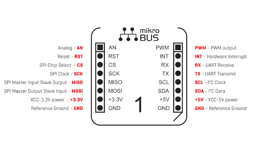
Although closely related to mikroBUS™ via the interface defined by 12 mikroBUS™ pins (excluding power pins – VCC, GND), board def file - in theory, can be written for a development system which doesn’t have a mikroBUS™.
Fortunately, the board def file has very strict rules when it comes to defining function names, which allows using the existing board def file with peripherals and GPIOs as a template for writing a board def file for your own development system, with minimal changes.
To demonstrate this, we will use Shield for the mikromedia Plus for STM32F4 development system and build the required mikroSDK files.
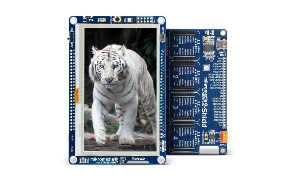
The mikromedia Plus for STM32F4 has the STM32F407ZGT6 MCU equipped, so by selecting this MCU in the Project Settings panel of the compiler, a new node in the Library Manager will appear, labeled as easyMX_STM32_generic, located inside the mikroBUS API section. The simplest and easiest method of getting the new board def file is to adjust the existing generic board def source code. This method will be explained in more details, in the next section.
The other way is to copy the content of the files of the generic board def into new files, named by the system we want to use, which will leave the generic board source untouched, so it can be used as a template for even more development systems that we might want to include at a later point in time.
The board def itself consists of several files, sorted according to their purpose. The file name is enough to give us a hint about the purpose of the specific file:
- easymx_STM32_generic.c Board def common interface - src
- easymx_STM32_generic.h Board def common interface - header
- __easymx_STM32_generic_GPIO.c Board def GPIO module
- __easymx_STM32_generic_UART.c Board def UART module
- __easymx_STM32_generic_LOG.c Board def LOG module
- __easymx_STM32_generic_SPI.c Board def SPI module
- __easymx_STM32_generic_I2C.c Board def I2C module
All of these files include the __t_STM32.h which contains definitions for the mikroC PRO for ARM compiler specific types, related to the STM32 vendor. It is not required to edit the __t_STM32.h file, because the types are the same for all the MCUs.
Inside common board def
#include "__t_STM32.h"

#ifndef __STM32_BOARDEF__
#define __STM32_BOARDEF__

// -------------------------------------------------------- BOARD CONFIGURATION /

#define __MIKROBUS1
#define __MIKROBUS2
#define __MIKROBUS3
#define __MIKROBUS4
//#define __MIKROBUS5
//#define __MIKROBUS6

//#define __LOG_USBUART
//#define __LOG_USBUART_A
//#define __LOG_USBUART_B
easymx_STM32_generic.h
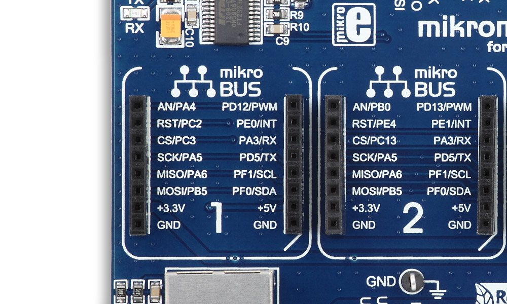
Compared to the generic board, the Shield for mikromedia Plus for STM32F4 has 4 mikroBUS™ slots, so the two related def files should be uncommented. There is no built-in USB to UART module on the Shield itself, so all the LOG related defines be commented out.
The rest of the content of the generic board def files don't need to be changed. These two files can be observed as a board def interface whose parts need to be implemented into separate modules. Those modules are implemented through the rest of the files and every file represents an individual module i.e. peripheral, GPIO or special application module, like the logger module.
In the following section, we’ll go through every module, supported so far.
The GPIO module
The GPIO module _STM32_GPIO.c is probably the best module to start with. It maybe requires the most work, but at the same time, it is also the easiest to understand, because the functions and the registers it uses are very well known among embedded developers. Every embedded developer out there started working with the simple GPIO operations, such as the pin direction setting and the pin status (logical 0 / 1).
If you take a closer look, you’ll notice that the file starts with the function definitions – the names of those functions begin with the get or set, then there is the name of the mikroBUS™ pin in capital letters and finally, a digit separated with the "_" character. The first segment represents an information about the purpose of the function – if it gets or sets the pin status. The second segment is the pin position on the mikroBUS™ and the third one represents the number of mikroBUS™ sockets.
The main difference between these functions lies in the get and set function prototypes. Get functions don’t have any parameters – they just return the status value of the pin, while set functions have one parameter used to set the pin status.
For example, the function that sets CS pin status on the mikroBUS™ 3 needs to have the following prototype and name: void _setCS_3( uint8_t value) and it needs to implement an operation which sets the pin status depending on the value forwarded by the function parameter (0=GND, 1=VCC).
By taking one quick look at the schematic or even the PCB itself, we can mold the template file in what we need. Functions for mikroBUS™ should look like this:
static uint8_t _getAN_1  ()           { return GPIOA_IDR.B4 ; }
static uint8_t _getRST_1 ()           { return GPIOC_IDR.B2 ; }
static uint8_t _getCS_1  ()           { return GPIOC_IDR.B3 ; }
static uint8_t _getSCK_1 ()           { return GPIOA_IDR.B5; }
static uint8_t _getMISO_1()           { return GPIOA_IDR.B6; }
static uint8_t _getMOSI_1()           { return GPIOB_IDR.B5; }
static uint8_t _getPWM_1 ()           { return GPIOD_IDR.B12 ; }
static uint8_t _getINT_1 ()           { return GPIOE_IDR.B0; }
static uint8_t _getRX_1  ()           { return GPIOA_IDR.B3 ; }
static uint8_t _getTX_1  ()           { return GPIOD_IDR.B5 ; }
static uint8_t _getSCL_1 ()           { return GPIOF_IDR.B1 ; }
static uint8_t _getSDA_1 ()           { return GPIOF_IDR.B0 ; }
static void _setAN_1  (uint8_t value) { GPIOA_ODR.B4  = value; }
static void _setRST_1 (uint8_t value) { GPIOC_ODR.B2 = value; }
static void _setCS_1  (uint8_t value) { GPIOC_ODR.B3 = value; }
static void _setSCK_1 (uint8_t value) { GPIOA_ODR.B5 = value; }
static void _setMISO_1(uint8_t value) { GPIOA_ODR.B6 = value; }
static void _setMOSI_1(uint8_t value) { GPIOB_ODR.B5 = value; }
static void _setPWM_1 (uint8_t value) { GPIOD_ODR.B12  = value; }
static void _setINT_1 (uint8_t value) { GPIOE_ODR.B0 = value; }
static void _setRX_1  (uint8_t value) { GPIOA_ODR.B3  = value; }
static void _setTX_1  (uint8_t value) { GPIOD_ODR.B5  = value; }
static void _setSCL_1 (uint8_t value) { GPIOF_ODR.B1  = value; }
static void _setSDA_1 (uint8_t value) { GPIOF_ODR.B0  = value; }
The second part of the GPIO module is about the pin direction setting and it can be considered as a part of the initialization. New operations can be added inside of these functions, if necessary. For example, some PIC microcontrollers require clearing the ANSEL register, in case the pins are used as digital.
In our case, in mikroC pro ARM compiler for STM32 microcontrollers it’s enough to call ‘GPIO_Digital_Input’‘GPIO_Digital_Output’
It is not difficult to understand where you need to make changes in order to get the function working within our development system, just by looking at the names of the function names and implementation. Only a few characters will need to be changed.
static T_mikrobus_ret _gpioInit_1(T_mikrobus_pin pin, T_gpio_dir dir)
{
    switch( pin )
    {
        case _MIKROBUS_AN_PIN    : if(dir == _GPIO_INPUT) GPIO_Digital_Input(&GPIOA_BASE, _GPIO_PINMASK_4 );
                                   else GPIO_Digital_Output(&GPIOA_BASE, _GPIO_PINMASK_4) ; break;
        case _MIKROBUS_RST_PIN   : if(dir == _GPIO_INPUT) GPIO_Digital_Input(&GPIOC_BASE, _GPIO_PINMASK_2 );
                                   else GPIO_Digital_Output(&GPIOC_BASE, _GPIO_PINMASK_2) ; break;
        case _MIKROBUS_CS_PIN    : if(dir == _GPIO_INPUT) GPIO_Digital_Input(&GPIOC_BASE, _GPIO_PINMASK_3 );
                                   else GPIO_Digital_Output(&GPIOC_BASE, _GPIO_PINMASK_3) ; break;
        case _MIKROBUS_SCK_PIN   : if(dir == _GPIO_INPUT) GPIO_Digital_Input(&GPIOA_BASE, _GPIO_PINMASK_5);
                                   else GPIO_Digital_Output(&GPIOA_BASE, _GPIO_PINMASK_5); break;
        case _MIKROBUS_MISO_PIN  : if(dir == _GPIO_INPUT) GPIO_Digital_Input(&GPIOA_BASE, _GPIO_PINMASK_6);
                                   else GPIO_Digital_Output(&GPIOA_BASE, _GPIO_PINMASK_6); break;
        case _MIKROBUS_MOSI_PIN  : if(dir == _GPIO_INPUT) GPIO_Digital_Input(&GPIOB_BASE, _GPIO_PINMASK_5);
                                   else GPIO_Digital_Output(&GPIOB_BASE, _GPIO_PINMASK_5); break;
        case _MIKROBUS_PWM_PIN   : if(dir == _GPIO_INPUT) GPIO_Digital_Input(&GPIOD_BASE, _GPIO_PINMASK_12 );
                                   else GPIO_Digital_Output(&GPIOD_BASE, _GPIO_PINMASK_12) ; break;
        case _MIKROBUS_INT_PIN   : if(dir == _GPIO_INPUT) GPIO_Digital_Input(&GPIOE_BASE, _GPIO_PINMASK_0);
                                   else GPIO_Digital_Output(&GPIOE_BASE, _GPIO_PINMASK_0); break;
        case _MIKROBUS_RX_PIN    : if(dir == _GPIO_INPUT) GPIO_Digital_Input(&GPIOA_BASE, _GPIO_PINMASK_3 );
                                   else GPIO_Digital_Output(&GPIOA_BASE, _GPIO_PINMASK_3) ; break;
        case _MIKROBUS_TX_PIN    : if(dir == _GPIO_INPUT) GPIO_Digital_Input(&GPIOD_BASE, _GPIO_PINMASK_5 );
                                   else GPIO_Digital_Output(&GPIOD_BASE, _GPIO_PINMASK_5) ; break;
        case _MIKROBUS_SCL_PIN   : if(dir == _GPIO_INPUT) GPIO_Digital_Input(&GPIOF_BASE, _GPIO_PINMASK_1 );
                                   else GPIO_Digital_Output(&GPIOF_BASE, _GPIO_PINMASK_1) ; break;
        case _MIKROBUS_SDA_PIN   : if(dir == _GPIO_INPUT) GPIO_Digital_Input(&GPIOF_BASE, _GPIO_PINMASK_0 );
                                   else GPIO_Digital_Output(&GPIOF_BASE, _GPIO_PINMASK_0) ; break;
        default                  : return _MIKROBUS_ERR_PIN;
    }
    return _MIKROBUS_OK;
}
Peripherals
Peripheral modules require fewer changes. You need to change just a couple of characters, in some cases - the whole identifiers, and then the module can be used in our development system. To successfully accomplish this task, you will need to take a look at the datasheet for certain MCU found on your development board, to determine which peripheral exactly is located on a particular pin, reserved for that type of peripherals.
When it comes to ARM compilers, in most cases, by using the ‘crtl+space’ shortcut, you’ll be able to narrow down the number of possible modules to a certain peripheral and based on the “module struct” structure, to determine which peripheral exactly is needed.
Every peripheral module has one structure and one function for a specific mikroBUS™. Structure names are very clearly defined and contain functions, related to peripherals for a specific mikroBUS™. The number of structures for every peripheral is equal to the number of mikroBUS™ sockets on the system, in this case on the Shield.
const T_i2c_obj _MIKROBUS1_I2C =
{
    I2C3_Start,
    I2C3_Write,
    I2C3_Read
};
Also, from the functions name you can easily see which module needs to be initialized; of course, that’s the module with the same ordinal number as found in the function of the structure.
static T_mikrobus_ret _i2cInit_1(const uint32_t* cfg)
{
    I2C3_Init_Advanced( cfg[0], &_GPIO_MODULE_I2C3_PA8_PC9 );
    return _MIKROBUS_OK;
}
With some architectures, is not enough to just initialize the peripheral; you need to do some additional operation like the aforementioned ANSEL registers in case of the PIC architecture or calling PPS functions in mikroC PRO for
The right place for calling these functions is the aforementioned mikroBUS™ peripheral related function.
Exception from the standard implementation of the init function are cases where it is necessary to forward explicit value as an argument to the compiler library, i.e. it is impossible to give a function parameter as an argument to the compiler function and in that case, the initialization function is called from a simple switch statement.
For more information, check the implementation of UART on AVR and PIC compilers.
The logger
The easiest way of showing output results from a sensor or any other device or program is to enable simple information logging on UART. All the major development systems have a USB-UART port, which enables you to connect to the computer USB. This way, you can monitor the sensor status, the output of any other peripheral or the status of the program execution in general. In case, there’s no USB-UART port, you can use one of the several USB to UART click boards™ (USB UART click, USB UART 2 click, USB UART 4 click or RS232 click), depending on the PC’s motherboard.
Logger module is the most similar to the UART module; logger is basically a UART module, where initialization is always 8N1. However, keep in mind that some alterations are required. You need to change the UART peripheral module’s number, according to the number used in your development system (i.e. check which UART module is routed to the integrated USB-to-UART IC). Also, it is necessary to change the assignment of the pointer to the logger variable, which will be used for the private generic _log_write_ fucntion.
static T_mikrobus_ret _log_write(uint8_t *data_)
{
    logger( *data_ );
    return 0;
}

static T_mikrobus_ret _log_init1(uint32_t baud)
{
    UART2_Init_Advanced(baud, _UART_8_BIT_DATA, _UART_NOPARITY, _UART_ONE_STOPBIT, &_GPIO_MODULE_USART2_PD56);
    logger = UART2_Write;
    return 0;
}
Conclusion
If you are very familiar with your favorite development system, creating a board def file for your own development system won’t take more than 10 minutes.
This was a tutorial for the mikroC PRO compilers. The same method can be used for the other two programming languages: mikroBasic and mikroPascal.
The real question here is “what do I get out of this”. The answer is: by following the mikroSDK standard you get immediately usable click board application code for every mikroBUS™ compliant click board™, independent on the used development platform.