


Table of contents
Getting started
Wake up
Six capacitive buttons surrounding an OLED display make up Hexiwear's user interface.
A double tap on any of the buttons will wake up the device and light up the OLED display to show the home screen.
If double taps don't wake up the device, the battery is probably empty. Connect Hexiwear to a power supply through the Micro USB port on the side. Charge for a while then try again.
From the home screen, a single tap on the lower right button will bring you into the menu. Use the pair of buttons to the right side of the screen to browse through the list of available items. Two dots on the right edge of the screen are visible wherever vertical scrolling is available.
The two buttons below the screen are for entering and exiting folders or turning settings on and off.
If you are left-handed, you can set up your Hexiwear so that the buttons on the left side of the screen are used for vertical scrolling. From the Home Screen, go to Menu >>> Settings >>> Active buttons.
Reset
If the Hexiwear unit becomes unresponsive, you can reset it using the button on the rear side. You will need a pin, needle, paper clip, or similar item to press reset (same type of tool used for ejecting SIM cards out of cell phones).
Hardware features
Buttons, ports and LEDs
Hexiwear has a hexagonal form factor suitable for a wearable or a standalone device deployed in the field. Here's what you see from the outside:

- Ambient light sensor
- One of six capacitive buttons surrounding the central OLED display
- RGB LED
- Hexiwear Docking Station connector
- Optical heart rate sensor LED and photodiode
Not visible here, Hexiwear also a Micro USB port on the upper left edge (looking from the front)
Specifications
The following is a full list of components inside Hexiwear with links to relevant data sheets.

- MCU: NXP Kinetis K64 MCU (ARM® Cortex®-M4, 120 MHz, 1M Flash, 256K SRAM)
- BLE: NXP Kinetis KW4x (ARM® Cortex®-M0+, Bluetooth Low Energy & 802.15.4 Wireless MCU)
- 3D Accelerometer and 3D Magnetometer: NXP FXOS8700CQ
- 3-Axis Digital Gyroscope: NXP FXAS21002
- Absolute Digital Pressure sensor: NXP MPL3115A2R1
- 600 mA Single-cell Li-Ion/Li-Polymer Battery Charger: NXP MC34671
- Light-to-digital converter: TAOS TSL2561
- Digital humidity and temperature sensor: MEAS HTU21D
- Heart-rate sensor: Maxim’s MAX3010x
- 1.1” full color OLED display
- Haptic feedback engine
- 190 mAh 2C Li-Po battery
- Capacitive touch interface
- RGB LED
- 8 MB of additional Flash memory
Schematic
The Hexiwear schematic is available as a printable PDF file
The Hexiwear Docking Station schematic is available as a printable PDF file
Built-in applications and settings
The following is an overview of all the applications and settings on Hexiwear.
Home screen

- Time and date (synced when paired with Hexiwear smartphone app. More information on cellphone app is below.)
- Battery status
- Ambient temperature
- Bluetooth connection status (blue when connected to smartphone)
- Smartphone notifications
Apps
Weather Station


Shows ambient temperature, humidity and pressure data in real time.
Motion


Displays readings from accelerometer and gyroscope in real time (single data point for each axis)
Flashlight

Toggles front-facing RGB LED.
Fitness – Pedometer


Step and calorie counter next to each other. Walking steps are inferred from accelerometer readings. Calories are calculated using a formula. "Stop" button resets count.
Fitness – Heart rate


Heart-rate readings from the optical sensor. Two wavelengths of light from two LEDs (red and green) are emitted from the small slit on the rear of Hexiwear. When you place your wrist or fingertip over the slit, the sensor measures the light absorbance of pulsing blood through a photodetector and derives heart-rate info. Current firmware version is able to show rough estimates.
Notifications


A more detailed overview of smartphone notifications visible from the home screen. Displays the number of missed calls, unread messages (from Gmail inbox) and unread SMS messages. Requires Hexiwear to be paired with a phone. Updated in real time.
Settings
Bluetooth

Toggles bluetooth on and off. White when turned OFF, Blue when turned ON.
OTAP


OTAP stands for "Over the Air Programming e.g. wireless firmware updating. You can choose to update either the KW64 (main MCU) or the KW40 (BLE chip). Requires Hexiwear smartphone app. See this video for instructions.
Active buttons

Sets active buttons to either left or right side (used for vertical scrolling). Left-handers will want to set it to the left, in order not to obstruct their view of the screen while tapping buttons.
Haptic

Toggles haptic feedback engine on and off. White when turned OFF, Blue when turned ON. Haptic engine gives tactile feedback on button presses. Deactivating it conserves battery.
Get app

Displays QR codes for fetching and installing the Hexiwear smartphone app. Choose between Android and iOS. Requires a QR Code reader on your smartphone. Alternatively, you can download the apps directly from Google Play or the iTunes store.
About

Manufacturer info, hardware and firmware version.
Reset

Software reset button.
Sensor tag mode

Toggles Sensor tag mode. When active, Hexiwear will continually broadcast readings from all its internal sensors over BLE. The readings can be accessed from the Hexiwear smartphone app, or directly from the WolkSense cloud. White when turned OFF, Blue when turned ON.
Hexiwear smartphone apps
The Hexiwear smartphone app will significantly expand the functionality of your Hexiwear. It will allow you to remotely access the readings from all of Hexiwear's sensors, and log the data into a cloud. Since Hexiwear uses Bluetooth Low Energy for wireless communication, you will need a phone that supports Bluetooth 4.1.
Installing the smartphone app
Android app (version 4.4 and up): GitHub
iOS app ( version 8.4 and up): iTunes (compatible with iPhone, iPad, and iPod touch)

Pairing Hexiwear with smartphone
Video walkthrough
A video walkthrough on using the Hexiwear app is available on Youtube. Minor differences from the current version of application may exist.
Step by step
- Turn ON Bluetooth on Hexiwear
- Turn on Sensor Tag mode on Hexiwear
- Launch Hexiwear app from your phone
- The app will prompt you to turn ON the Bluetooth on your phone
- Log-in to your WolkSense acconut (first time users will need to register, it's free)
- From the main screen, swipe down to scan for available Hexiwear devices; select one.
- A six digit passkey will appear on Hexiwear's display. At the same time the smartphone app will prompt you to type in the passkey.
- Hexiwear is now connected to your smartphone. Sensor readings will appear shortly.
Troubleshooting
If errors occur, to restart the pairing process, go to the Bluetooth settings on your smartphone and "forget" the Hexiwear device. This removes all the initialization data and enables you to start over.
Wolksense cloud platform
By registering an account in Hexiwear's smartphone app, you automatically gain access to the WolkSense cloud. To send Hexiwear sensor readings to the cloud do the following:
- Pair Hexiwear with smartphone
- Make sure that Hexiwear is in Sensor Tag mode
- Enable "Publish to cloud" inside the smartphone app settings menu
- Go to app.wolksense.com, and log-in with the same username and password you use for the Hexiwear smartphone app.
Once logged in, you will be able to use all the functionalities that the Wolksense platform offers: sensor readings, alarms, reports and more.
Sensor readings
The first thing you see when you log-in to the Wolksense cloud is a dashboard with sensor readings. The dashboard is customizable so you will be able to choose which sensor readings you want to see.
By default, Hexiwear will publish sensor readings every 10 seconds. You can increase the interval to 30 seconds, 1 minute, or 5 minutes from within the smartphone app.
Setting up alarms
The Wolksense platform also allows you to configure thresholds for each sensor to set off alarms when certain low or high values are reached. To set alarms, click on the "Sensors" tab and open the Hexiwear device settings. You can apply different settings for individual sensors.
Creating reports
The "Reports" tab on the Wolksense cloud will allow you to generate reports of logged sensor readings. Graphs give you daily, weekly and monhtly views. It is also possible to export data into a CSV file.

Hexiwear sensor readings on Wolksense cloud

Setting alarms in the Device settings menu from the SENSORS tab

A graph showing room temperature changes over a half hour period, measured by Hexiwear
Hexiwear Docking Station


The Hexiwear Docking Station is an expansion board that provides an interface for programming, debugging, and enhancing Hexiwear with additional functionalities (by adding click boards™). The Docking Station vaslty increases the possibilities of Hexiwear as a development tool. For more information, read the Docking Station User Guide.
Resources
- Hexiwear official landing page
- Hexiwear on Kickstarter
- Dedicated repository on MikroElektronika's GitHub channel
- Hexiwear Docking Station user guide
- Hexiwear Creating Your First project guide
- NXP Semiconductors Hexiwear page
- Homepage of WolkSense, cloud solution provider for Hexiwear
- MikroElektronika's Technical Support hub
Software and Tools Environment Setup
Step 1: Jump Start Your Design with the NXP Kinetis SDK!
Kinetis SDK is a complementary collection of comprehensive software enablement for NXP Kinetis Microcontrollers that includes system startup, peripheral drivers, USB and connectivity stacks, middleware, and real-time operating system (RTOS) kernels. Hexiwear is developed based on Kinetis SDK Version 1.3. Click below to download the SDK Release appropriate for your computer's operating system, the link to Kinetis SDK is:
Step 2: Install the NXP KDS Toolchain
The Kinetis Design Studio (KDS) is a complimentary integrated development environment for Kinetis MCUs that enables robust editing, compiling and debugging of your designs. Based on free, open-source software including Eclipse, GNU Compiler Collection (GCC), GNU Debugger (GDB), and others, the Kinetis Design Studio IDE offers designers a simple development tool with no code-size limitations. Hexiwear default software can be modified in the KDS.
Download the latest version on KDS.
Step 3: Serial UART Driver
Many of the example applications output data over the MCU UART so make sure that the driver for the board's virtual COM port is installed. Before you run the driver installer, please make sure you have Hexiwear on docking station and docking station plugged in to your PC. For More instruction on how to put Hexiwear on docking station, watch the video at www.hexiwear.com/1769-
Download the serial UART driver.
With the serial port driver installed, run your favorite terminal application to view the serial output from the MCU's UART. Configure the terminal to 115,200 baud rate, 8 data bits, no parity and 1 stop bit. To determine the port number of the Hexiwear's virtual COM port, open the device manager and look under the "Ports" group.

Step 4: Download Hexiwear Hardware / Software / Documentation package
- Go to the Hexiwear Github repository located at: github.com/MikroElektronika/HEXIWEAR
- Select Clone or download and choose Download ZIP in the popup window
- Once the download is complete, extract the content of the HEXIWEAR-master.zip on your computer.

Step 5: Install Eclipse Updates
Before using Kinetis Design Studio IDE with Kinetis SDK, the Kinetis SDK Eclipse update must be applied. Without this update, Eclipse cannot generate Kinetis SDK-compatible projects.
Windows and Mac® OS Users
Open Kinetis Design Studio. The program will ask you to select a workspace. Select default workspace.

From Kinetis Design Studio toolbar, select Help then Install New Software

In the Install New Software dialog box, click the Add button in the upper right corner. Then, in the Add Repository dialog, select the Archive button

In the Add Repository archive dialog box, browse the Kinetis SDK install directory. Find the following file:
/tools/eclipse_update folder and select the KSDK_ _Eclipse_Update.zip

Click Open and the OK button in the Add Repository dialog box.
The Kinetis SDK update shows up in the list of the original Install dialogs

Check the box to the left of the KSDK 1.3.0 Eclipse Update and click the Next button in the lower right corner. Follow the remaining instructions and Accept the licensing to finish the installation of the update. After the update is applied, restart KDS for the changes to take effect.
Step 6 Install PyOCD Eclipse Add-in
In order to program/debug Hexiwear via its docking featuring an ARM DAP-LINK Debug, virtual Serial and Flash programming interface, we need to upgrade Eclipse with the PyOCD plug-in.
The PyOCD plug-in requires first to install Python software
From your web browser download Python 2.7.11 installer at: www.python.org/downloads

Double click on the installer located in your download directory and follow the instructions.
Download the Zip package for the PyOCD Eclipse Plugin
From Sourceforge at https://sourceforge.net/projects/gnuarmeclipse/files/Eclipse/ and select the latest version shortcut (see picture below)
The ilg.gnuarmeclipse.repository-3.2.1-201701141320.zip file is also available from Hexiwear Github repository in the folder SWpyOCD
Copy the Zip package to the folder C:Freescale of your computer hard-drive

Now let’s upgrade Eclipse with PyOCD plug-in.
a. Select from KDS toolbar Help >> Install New Software…

b. In the new window, choose Add… then Archive…
c. Select the file ilg.gnuarmeclipse.repository-3.2.1-201701141320.zip available at C:Freescale and click on Open… and OK

d. Check the box next to GNU ARM C/C++ Cross Development Tools TO SELECT ALL THE OPTIONS (see picture below) and click on Next
e. Accept the license agreement then Click on Finish…

f. Kinetis Design Studio will restart to complete the installation of the plugin
You must now install PyOCD GDB Server tool
The pyocd-gdbserver.exe file is also available from Hexiwear Github repository in the folder SWpyOCD

Copy the executable to KDS rooth folder folder C:FreescaleKDS_v3

Building and debugging the first program
Basics of Kinetis Design Studio
Several Tutorials available on web:
- MCU on Eclipse: How to use Kinetis Design Studio
- Kinetis Design Studio 3.0 Kinetis SDK 1.2 Processor-Expert using FRDM-KL43Z: Quick tutorial on GPIO Interrupt (Toggling LED using button with Interrupt logic)
- FRDM K64F - blinking an LED using #Kinetis Design Sudio and Processor Expert
Step 1: Importing Hexiwear Project in Kinetis Design Studio
Let’s now build with the NXP KDS toolchain a project example for the Hexiwear board. First, open Kinetis Design Studio, then follow these steps:
- Select File, Import from the KDS IDE menu. In the window that appears, expand the General folder and select Existing Projects into Workspace. Then press the Next button.
- Click the Browse button next to the Select root directory: option
- Point to the project folder for the K64 device, which can be found in the HEXIWEAR-master package using this path:
HEXIWEAR-masterSWMK64
4. Press OK, then Check the box to the left of the HEXIWEAR_MK64 and HEXIWEAR_Bootloader_() project and click the Finish button in the lower right corner.

Step 2: Building Hexiwear Project
Select the HEXIWEAR_MK64 project in the project explorer window and click on the Build icon (hammer) from the toolbar.
Be patient, the first compilation of this advanced project (display, communication…) might last few minutes depending from your computer configuration. Compilation will end up with few Warnings…

Step 3: Placing Hexiwear unit on Docking Station
For More instruction on how to put Hexiwear on docking station, watch the video at www.hexiwear.com/1769-2/
Plug the Hexiwear board to the Docking Station via the specific connector.

Hexiwear Docking Station embeds a hardware debug interface called OpenSDA By default it is preprogrammed with the ARM DAP-LINK OpenSDA Application, which delivers Debug, Virtual Serial and Flash Programming services.

Hexiwear embeds two MCUs, a Kinetis K64F as main MCU and a KW40Z as BLE MCU On the Docking Station please make sure that you have the correct jumper configuration, to debug the Kinetis K64F: 11001111

One USB to micro-USB cable is included in the Docking Station packaging. Connect one end of the USB port to your computer and the other end to the micro-USB port of the Docking station.

Windows should detect a new peripheral
To properly finish the installation of the OpenSDA / DAP-LINK drivers, you must download and install the ARM mbed Serial drivers at the address below As a confirmation, check in the Peripheral Manager that you don’t have peripherals unidentified and that the following devices are available:
- Portable Device: DAP-LINK
- Ports (COM & LPT): mbed Serial Port (COMxxx)
Step 4: Debug Configuration Settings
Let’s now launch the debug session for the Hexiwear project example with KDS toolchain.
Click on the small downward arrow next to the Debug (green bug) icon from the toolbar and select Debug Configurations…

In the Debug Configurations window, right click on GDB PyOCD Debugging and select New • From the right panel, in the Main tab, below Project press the Browse button and select the HEXIWEAR_MK64 and select OK

In order to program/debug Hexiwear via its docking featuring an ARM DAP-LINK Debug, virtual Serial and Flash programming interface, we need to upgrade Eclipse with the PyOCD plug-in. The PyOCD plug-in requires first to install Python software
From the Debugger tab, select the Browse button next to PyOCD Setup / Executable, choose the pyocd-gdbserver.exe and press OK

Click on the buttons Apply and Debug to launch the debug session

In the console, you should see the project starting to be programmed in the K64F MCU of the Hexiwear board

Press the Resume icon from the toolbar to start the application

Code Examples: Flashlight and Haptic Feedback
Excercise 1: Flashlight LED Tweaks
Open flashlight_driver.c. The source is shown in the image:

This code is designed for turning or of the RGB LED based on input from app on Hexiwear unit

Change Code for RED LED.

Press the Debug icon from the toolbar to start the application

Press the Resume icon from the toolbar to start the application
Now using flashlight app on Hexiwear, Red LED would turn on instead on RGB LED
Exercise 2: Change Haptic Feedback Duration
• Use the same file flashlight_driver.c
• Locate haptic_Vibrate() function.

• Open the haptic_Vibrate() function

• Changing the OSA_TimeDelay () value will change the vibration duration of the Haptic feedback motor on every click. Change the value to 200.
• Press the Debug icon from the toolbar to start the application.
Now on every click the haptic feedback would be longer.
Hexiwear Docking Station Features
The Hexiwear Docking Station is an expansion board for Hexiwear, the wearable IoT development kit. It provides an interface for programming, debugging, and enhancing Hexiwear with additional functionalities (by adding click boards™).
Hexiwear
Hexiwear is a standalone development kit for IoT, designed to look and feel like a consumer-grade device. Consult the < rel="nofollow">Hexiwear user guide for a detailed overview.
Features
Every feature of the Docking Station is intended to either expand Hexiwear's functionality or to provide an interface for changing and debugging its firmware. The two most important features are the three mikroBUS™ sockets, and the OpenSDA circuitry that allows you to program/debug Hexiwear through USB.
What's on board
The majority of components are on the front side.
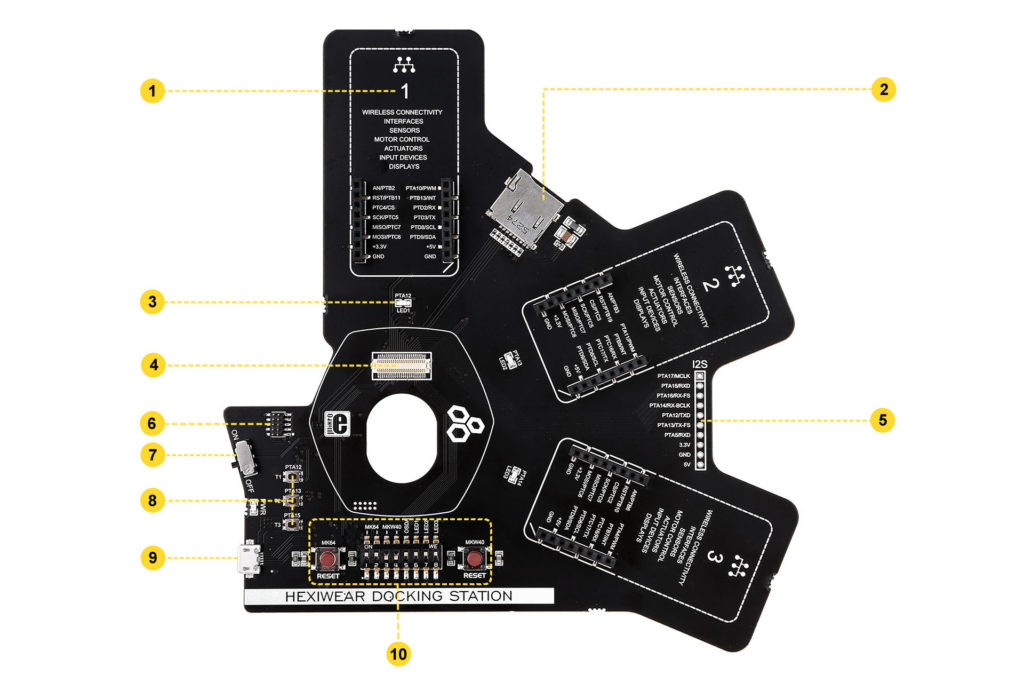
- mikroBUS™ socket for click boards™ (one of three)
- microSD slot (card not included)
- LED (one of three)
- Hexiwear connector that interfaces to Hexiwear's main MCU (K64x) and Wireless MCU (KW4x)
- I2S interface
- JTAG connector for external programmers
- ON/OFF switch
- Pushbuttons
- Micro USB port
- OpenSDA control interface
The OpenSDA programmer/debugger circuitry in on the rear of the board:

Buttons and switches close-up

There is a row of 8 configuration switches right under the Hexiwear connector. Switches 1-5 are for setting up the OpenSDA programmer/debugger to connect either to the K64 MCU or the KW4x BLE MCU.
In both cases, switch 5 should be set in the upper position (ON). The configuration in the image above is for programming and debugging K64 (switches 1,2 and 5 in the upper position, while 3 and 4 are in lower position). To program and debug KW4x, put switches 1 and 2 into the lower position, and switches 3-5 in the upper position.
To use the Docking station with an external programmer (through the JTAG connector), switch 5 should be in lower position.
The remaining switches (6-8) are for choosing whether PTA12, PTA13 and PTA14 pins are connected to the Docking Station LEDs (the pins can also be used as GPIOs (refer to the schematic to see how specific pins are routed).
Schematic

The Hexiwar Docking Station schematic is available as a printable PDF file
click boards

The click board eco-system vastly enhances Hexiwear's potential as a development tool. Hundreds of sensors, actuators, transceivers, displays, ports, encoders and interfaces are available on click boards – add-on boards with a standardized connector and form factor.
See all available click boards™ on MikroElektronika's website.
OpenSDA
OpenSDA is an open-standard serial and debug adapter. It bridges serial and debug communications between a USB host and a target board microcontroller (K64 and KW4x in case of Hexiwear). The hardware circuit is based on NXP Kinetis K20 family MCU and an integrated USB controller. OpenSDA features a mass storage device (MSD) bootloader.
Learn more in the official user guide.
Troubleshooting
Docking station appears as “MAINTENANCE” when connected to PC
If you have connected the Docking station to your PC, and it appears as “MAINTENANCE” without holding RESET button while turning the Docking station on, there are two possible reasons why this is happening.
I) First is that you somehow erased, or corrupted “DAPLINK” OpenSDA firmware, and you
can easily load the firmware again, just follow nex steps:
-Download hex file of the firmware from the following link:
https://github.com/MikroElektronika/HEXIWEAR/tree/master/HW/HEXIWEAR_DockingStation
-Just copy it to the “MAINTENACE” mass storage.
II) Second possible reason is that you somehow erased, or corrupted one of the MCUs that is turned on on the DIP switch on the Docking station at the moment. This is happening because if your Hexiwear’s MCU is empty, the docking station with the Hexiwear on it would appear in “MAINTENANCE” mode.
What you should do is this (In case that MK64 is erased):
Turn off all switches on the Docking station except of the OSDA, which needs to be turned on. Connect the Docking station with Hexiwear on it to your PC and then turn the Docking station on.
While the Docking station itself is turned on, put the MK64 switches in the ON possition, and use our mikroProg suite for ARM to write this bin file to Hexiwear’s MCU:
mikroProg suite can be downloaded from here:
This is how mikroProg suite needs to be set in order to program the Hexiwear:

Note that you will have to install mbed serial driver for your Docking station. If you didn’t already do that, you can download drivers from here:
https://developer.mbed.org/handbook/Windows-serial-configuration