A quick look at your phone and you know the temperature in your living room. One text message turns the lights around the whole house, and another one regulates the thermostat. It's a simple truth that smart home devices make our lives easier.
So, why wouldn't you try to make a smart home application yourself?
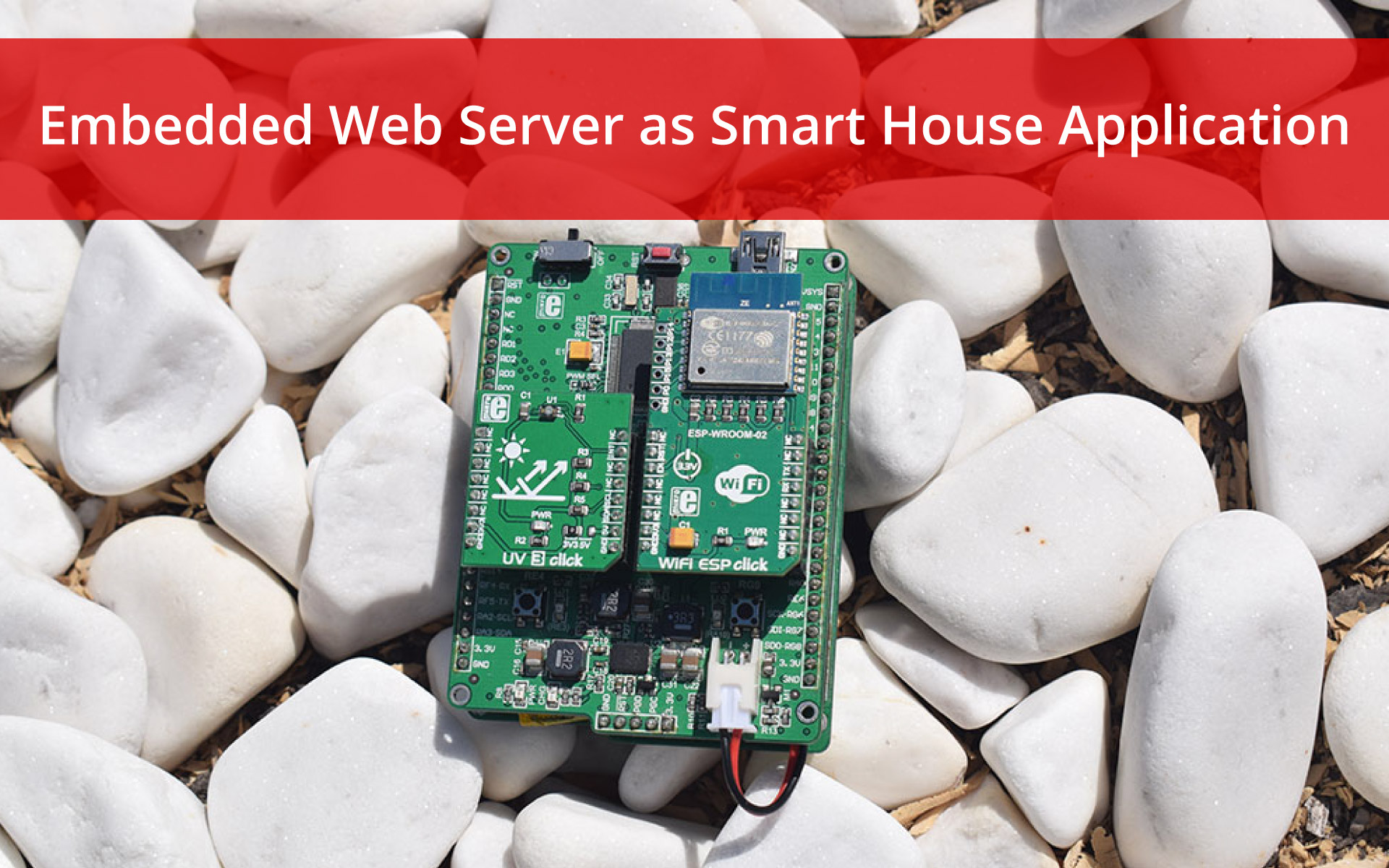
That is why we prepared a project which uses WiFi ESP click as the main part. We also have a UV and temperature sensors used on end nodes which provide information to our web server. There are no turning lights on or off, but you can check you house temperature or measure outside UV radiation from any part of the world. Everything is built using MikroE development tools and this tutorial will guide you through every single step.
It is important to say that our end nodes are battery powered, which is not mandatory. You can plug in the USB cable and give a power to you end node without care for battery life. Also, the PIC32 architecture is chosen for this project as one of the most popular, but also any other architecture can be used and all you have to do is to modify peripheral initialization routines and change pins.
Node 1
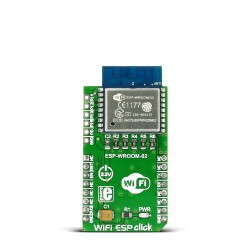
- Wifi ESP click
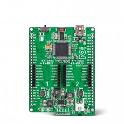
- Clicker 2 for PIC32MX
- Thermo K click
THERMO K click carries the MCP9600 IC from Microchip. Depending on the type of probe it uses the click can measure temperatures from −200 °C to +1372 °C. The click is designed to run either on 3.3V or 5V power supply. It communicates with the target MCU through I2C interface.

Yes I know, that this is not the main purpose of MCP9600, but this measurement of temperature above the stove can give you an idea how else this click board can be used.
Node 2
- Wifi ESP click
- Clicker 2 for PIC32MX
- UV 3 click.
UV 3 click is an advanced ultraviolet (UV) light sensor with I2C protocol interface. The click carries VEML6070 UVA light sensor designed by the CMOS process. UV 3 click runs on either 3.3V or 5V power supply.

And the UV 3 click?
As you can see we took it to the harsh August sun. It was mid noon, so the sun was at its prime moment, also it helped me to check the distance which can be achieved using ESP8266 - 30 meters, far enough for me.
Server
- Wifi ESP click
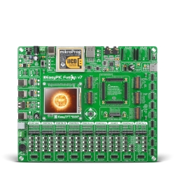
- EasyPIC Fusion V7 with PIC32MX795F512L
The server is built using WiFI ESP click which carries ESP-WROOM-02 that integrates the ESP8266 module. This module has built in TCP/IP stack alongside with some functionalities useful to build the web server easily. Both sides (end nodes & server) use this click board™ for communication and both sides use the AT parser slightly adapted for this purpose.

The end user can simply access the server using a tablet, a smartphone, or any other device which have web browser. Also you can redirect ports on your home router and make server accessible outside of your private network and make your smart home visible from outside.
WiFi ESP Commands
For starters, it is essential for us to know how WiFi ESP click basic commands. In its default configuration, ESP runs in the Serial Modem module. We communicate with it using AT commands. When we send a command, we expect a response from ESP. Response: OK indicates that the command has been successfully executed, ERROR indicates that there was a problem with running the command.
AT commands are divided into three groups:
- Basic (they start with AT + command name)
- WiFi module setup commands (they start with AT+CW .... Command name),
- TCP server setup commands (they start with AT+CIP ... command name).
While usage of basic commands is pretty clear we will pay attention to some of the module setup and TCP setup commands.
Server Commands
WiFi module setup commands
AT+CWMODE - with this command, we place our WiFi in one of the three modules. For example: AT+CWMODE = 1, one indicates that ESP is set to client mode, AT+CWMODE = 2 indicates that ESP8266 is in Server mode and AT+CWMODE = 3 indicates that ESP is in dual mode (at the same time Server and Client) . We need this very mode because the server we are creating should be in the server mode in which we receive information from clients and to be in the client mode to connect to its IP address on the website.
AT+CWJAP - The command allows us to connect the WiFi ESP click to a local wifi network. The parameters that are assigned to the command are SSID and Password of the local WiFi to which we are connected.
TCP server setup commands
AT+CIPSTATUS is a command that returns ESP status to a TCP server. As a response, we can get 3 values: 1. Status: 2 indicates that ESP is in the mode of creating its IP address, 2. Status: 3 indicates that it connects to the wifi, 3. Status: 4 indicates that it was disconnected.
AT+CIPMUX is the command which is used to determine whether the server will have single connections or multi connections (max 4 client).
The first command which is used to create a server:
AT + CIPSERVER = id, port, id represents what we want to do with the server:
- 0 is to delete the server,
- 1 to create a server, the default port is 333.
AT+CIPSTO? The command asks ESP8266 to return the response of our set timeout, server timeout, range 0 ~ 7200 seconds.
AT+CIPSR Is the most important command that generates a local IP address server.
After execution of this commands WiFi ESP click is in server mode. It is important to say that everything received from client is actually web page content. This means that end nodes are sending some pieces of the web page which is helpful to build dynamic web page where content is updated right after message reception.
To make a web page and send subtasks to it, we are using AT+CIPSEND command. Note that web page content is written in HTML, CSS, and Javascript, so it is necessary to convert message content to a string and to send it via UART.
The parameters needed to send the data to the web are the ID, the number of characters that web page has, and the content of the web page.
The ID under which the server is created is often the zero element, after which the clients who receive the indexes 1,2,3 and 4 are being pulled down. Now we have a complete server.
Client Commands
As I said, WiFi ESP click is also used for clients. The procedure is same, but instead of creating a web page, we will use the command AT+CIPSTART = id, tcp, addr, port which caries parameters needed for server connection. These are IP address, port, assignment ID and port.
After this command, we will use the AT+CIPSEND = id command when we want certain data to be forwarded. That ID will be the id that we assigned to the server with the previous command.
The first client has a task to read the temperature with Thermo K click and send this information to the server. The second client has a task to send information about the percentage of UV radiation (which is collected from the UV 3 click) to the server.
Now we have two devices that do not depend on each other and the information they collect is being sent to the server that displays them on the website, making our system scalable.
Summary
Source code and whole project can be found on Libstock.
Following this demonstration of server and clients communication, you can make your own smart home. Note that WiFi ESP (ESP8266) allows a maximum of 4 end nodes which enough for a simple smart house application.
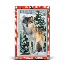
You can also use different types of sensors and devices for server and end nodes. For example you can use mikromedia Plus for PIC32MX7 instead of EasyPIC Fusion full development board and make some nice GUI which can display current measurements on built in TFT. With MikroE collection of 300+ click boards there is no uncovered type of measurement.


