


Unmanned aerial vehicles, or commonly known as "drones", are becoming more and more popular. People now use them for all sorts of tasks, from filming cool aerial shots with their camera, to exploring inaccessible parts of planet Earth, where the human foot cannot step. But, have you ever wondered how these machines maintain their balance and orientation? The answer is using gyroscopes and accelerometers. Our 10 Degrees of Freedom provides you with the Bosch BNO055 absolute orientation sensor, which contains a digital accelerometer, gyroscope, and magnetometer.
Each one of these provides you with three axis of orientation (x, y and z), add all that up, and you have 9 degrees of freedom, so where's the 10th? Our hardware engineers here at MikroElektronika decided to round it all up and give you a tool for full orientation measurement - the 10DOF click has one more chip from Bosch, the BMP180 pressure sensor, which will allow you to measure the altitude of your device. Source code and examples can be found on Github or Libstock.
Now let's do the math once again: 3 axis for measuring the acceleration and orientation of your device, 3 axis for measuring the angular velocity and position, 3 axis for measuring directions of magnetic fields around the device, and one pressure value for determining the altitude - our drone can never get lost ( we hope )!
Now we can go through all of these in more detail, so you can know how to program your vehicle and keep it from wandering around clueless.
Accelerometer
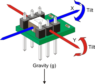
An accelerometer is a device that measures acceleration forces, or simply put, the rate of change of velocity of an object. The forces which change the velocity of our object can be static or dynamic. The best example of a static force is the gravitational force, which is constantly pulling us down with an acceleration of 9.8 m/s^2. Dynamic forces are those caused by movement or vibration of our device. So, when you check the values of your accelerometer, if it is laying flat on your working table, don't be suprised to see around 9m/s^2 on your Z axis. Your X and Y may also be active, since they can detect vibrations caused by your computer, your music playing loud, or that loud neighbor that just keeps moving furniture around their apartment all day.
Now let's go over the units of measurement. The unit for acceleration is meter per second squared ( m/s^2). Most accelerometers also offer one alternative, which is G (gravity). One G is the value of gravitational pull of our planet Earth, which is, as stated, 9.8 m/s^2. Put in perspective, if you push down your object hard enough, and measure 2 Gs, it would be as if the gravity here on Earth was twice as much as now - imagine weighing twice or three times as much as you do now, you would have a hard time moving, since your muscles are used to your original weight.
Accelerometers usually have a range of measurement. Usually it is stated in Gs. Our accelerometer can go from +- 2Gs to +-16Gs. You should choose which one suits your project best - if you want to register how much your car vibrates when running in 5th gear, +-2Gs will be mostly precise for you, however, if you want to measure how much your car accellerated while pushing the pedal to the medal in 5th gear, you might need a little bigger range.
Setting your desired range is simple with the library we provided, also you can set the unit of measurement to mili-Gs or m/s^2:
bno055_set_accel_range(0x04);
bno055_set_accel_unit(0x01);
How do accelerometers work?
Some accelerometers use the piezoelectric effect - they often contain microscopic crystal structures that change with acceleration forces, which causes a voltage to be generated. Another way is by sensing changes in capacitance : if you have two micro-structures next to each other, they have a certain capacitance between them. If an accelerative force moves one of the structures, then the capacitance will change. Converting from capacitance to voltage, you get an accelerometer. There are even more methods, including use of the piezoresistive effect, hot air bubbles, and light.
Setting off
Once you have set your desired range and unit of measurement, you can start measuring and experimenting with your accelerometer! There are also much more options and settings, but getting basic measures is the starting point. For more detailed settings you can always check out the documentation provided with our library.
Gyroscope
What's a gyroscope?
Gyroscopes are devices that measure or maintain rotational motion, or better put, measure angular velocity. Angular velocity, simply put, is speed in rotation. It is expressed in degrees per second (dps) or rotations per second (rps).
Gyroscopes determine orientation and are found in most autonomous navigation systems. When we want to balance our drone, a gyroscope can be used to measure rotation from the balanced position and send corrections to our motor.
A triple axis MEMS gyroscope, similar to the one we have on the 10DOF, can measure rotation around three axes: x, y, and z. The measurements are used to maintain the balance of our object. Airplanes also use gyroscopes to maintain their balance.
How do gyroscopes work?
The MEMS part of the gyroscope sensor is tiny (between 1 to 100 micrometers, the size of a human hair). When the gyro is rotated, a small resonating mass is shifted as the angular velocity changes. This movement is converted into very low-current electrical signals that can be amplified and read by a host microcontroller.
Like accelerometers, gyros also have their range, it can be set using similar functions to those with the accelerometer:
bno055_set_gyro_range(0x04);
Setting off
Once you got your range set, you can freely go and write code for your drone or robot. Like with the accelerometer, there are different settings which you can use to better the quality of your measurement, you can look it up in the documentation of the provided library.
Magnetometer
Magnetometers are measurement instruments used for two general purposes: to measure the magnetization of a magnetic material, or to measure the strength and, in some cases, the direction of the magnetic field at a point in space. Our 10DOF click uses these measures as a compass, to help the device maintain orientation. Our magnetometer is a vector magnetometer, which means it measures the flux density value in a specific direction in 3 dimensional space. These values can help us determine which way is North, South, East and West.
Reading these values with our library is pretty easy:
bno055_convert_float_mag_x_uT(&mag_x);
bno055_convert_float_mag_y_uT(&mag_y);
bno055_convert_float_mag_z_uT(&mag_z);
The magnetic vector here is represented in units of micro-Tesla.
Initialization and usage of the 10DOF click
Now that you understand the basics of our click, you can get to work! Building a drone which will fly inside a volcano? A robot that can bring you coffee and not spill it? Whatever your project is, if you need balance - 10DOF has got it!
The 10DOF has 13 different operation modes, as stated in the datasheet, on page 20. On power-on, the device is in configuration mode, and not reading any values. This is the only mode in which all the writable register map entries can be changed.
If you don't want to change anything, you can change the mode to a desired one.
After setting the mode, you can set the range and unit for the gyroscope and accelerometer measurements, and you're ready to go!
Here's a simple example of working with the 10DOF click:
First, make sure you initialize the I2C bus, assert the correct I2C slave addresses, and call the initialization functions:
I2C1_Init_Advanced(400000, &_GPIO_MODULE_I2C1_PB67 );
Delay_ms(200);
bmp180.dev_addr = BMP180_I2C_ADDR;
bno055.dev_addr = BNO055_I2C_ADDR1;

bmp180_init( &bmp180 );
bno055_init( &bno055 );
Next, set the operation mode, and your desired units and ranges:
bno055_set_operation_mode(0x0C);
bno055_set_accel_range(0x02);
bno055_set_accel_unit(0x01);
bno055_set_gyro_range(0x04);
bno055_set_gyro_unit( 0x01 );
And the 10DOF is ready! Reading your desired values is easy:
These functions return float values of positioning on x, y and z axis of the gyroscope.
bno055_read_euler_h(&euler_h);
bno055_read_euler_p(&euler_p);
bno055_read_euler_r(&euler_r);
or you can read the angular velocity in degrees per second on the gyroscope.
bno055_convert_float_gyro_x_dps(&gyro_x);
bno055_convert_float_gyro_y_dps(&gyro_y);
bno055_convert_float_gyro_z_dps(&gyro_z);
The following functions return float values of x, y and z axis of the accelerometer in mili-Gs.
bno055_convert_float_accel_x_mg( &accel_x );
bno055_convert_float_accel_y_mg( &accel_y );
bno055_convert_float_accel_z_mg( &accel_z );
Last but not least, read the magnetometer values, also in a float data type.
bno055_convert_float_mag_x_uT(&mag_x);
bno055_convert_float_mag_y_uT(&mag_y);
bno055_convert_float_mag_z_uT(&mag_z);
There are many more functions available in the library provided, feel free to check them out, and use the 10DOF click to it's full potential!
Example
/******************************************************************************* * Title : RTC Implementation * Filename : rtc.c * Author : Viktor * Origin Date : 10/01/2016 * Notes : None *******************************************************************************/ /*************** MODULE REVISION LOG ****************************************** * * Date Software Version Initials Description * 08/12/15 .1 RBL Module Created. * *******************************************************************************/ /** * @file 10DOF_click.c * * @brief This module contains the example of the 10DOF click */ /****************************************************************************** * Includes *******************************************************************************/ #include "bmp180.h" #include "bno055.h" #include#include "DOF10_objects.h" /****************************************************************************** * Module Preprocessor Constants *******************************************************************************/ /****************************************************************************** * Module Preprocessor Macros *******************************************************************************/ /****************************************************************************** * Module Typedefs *******************************************************************************/ /****************************************************************************** * Module Variable Definitions *******************************************************************************/ struct bmp180_t bmp180; struct bno055_t bno055; uint8_t temp = 3; float accel_x; float accel_y; float accel_z; float gyro_x; float gyro_y; float gyro_z; float mag_x; float mag_y; float mag_z; int int_gyro_x; int int_gyro_y; int int_gyro_z; uint8_t range; char buffer[1]; char txt[10]; int16_t euler_h; int16_t euler_p; int16_t euler_r; int32_t temperature_int; float temperature_float; int32_t pressure; /****************************************************************************** * Function Prototypes *******************************************************************************/ void system_init( void ); void process_pressure( void ); void process_temperature( void ); void process_magnet( void ); void process_accel( void ); void process_gyro( void ); /****************************************************************************** * Function Definitions *******************************************************************************/ void system_init() { I2C1_Init_Advanced( 400000, &_GPIO_MODULE_I2C1_PB67 ); Delay_ms( 200 ); bmp180.dev_addr = BMP180_I2C_ADDR; bno055.dev_addr = BNO055_I2C_ADDR1; bmp180_init( &bmp180 ); temp = bno055_init( &bno055 ); GPIO_Digital_Input( &GPIOA_IDR, _GPIO_PINMASK_0 ); // Set PA0 as digital input } void process_pressure() { uint32_t temp_press; temp_press = bmp180_get_uncomp_pressure(); pressure = bmp180_get_pressure( temp_press ); } void process_temperature() { uint16_t temp; temp = bmp180_get_uncomp_temperature(); temperature_int = bmp180_get_temperature( temp ); temperature_float = ( float ) temperature_int; temperature_float *= 0.1f; } void process_magnet() { bno055_convert_float_mag_x_uT( &mag_x ); bno055_convert_float_mag_y_uT( &mag_y ); bno055_convert_float_mag_z_uT( &mag_z ); } void process_accel() { bno055_convert_float_accel_x_mg( &accel_x ); bno055_convert_float_accel_y_mg( &accel_y ); bno055_convert_float_accel_z_mg( &accel_z ); } void process_gyro() { bno055_read_euler_h( &euler_h ); bno055_read_euler_p( &euler_p ); bno055_read_euler_r( &euler_r ); } void main() { system_init(); bno055_set_operation_mode( 0x0C ); bno055_set_accel_range( 0x01 ); bno055_get_accel_range( &range ); bno055_get_operation_mode( &buffer ); bno055_get_accel_unit( &temp ); bno055_set_gyro_range( 0x04 ); bno055_get_gyro_range( &range ); while( 1 ) { process_gyro(); process_accel(); process_temperature(); process_pressure(); process_magnet(); // Do some magic with the data Delay_ms( 250 ); } }
Summary
Being one of the most ubiquitous sensors on the planet, accelerometers, gyros, and magnetometers are found in everything from small children's toys, phones, to large aircraft, and ships. Making use of each of the physical world measurements enable an application to expand capabilities that can co-exist in a physical world. Drones are a common example but can be used in applications such as health care. Devices can sample the outside world and the patient they are attached to and can keep the elderly from falling or even tripping. Mastery of this technology is a valuable element in any embedded project.
References
wikipedia.org "Accelerometer" wikipedia 2016
wikipedia.org "Gyroscope" wikipedia 2016
science.howstuffworks.com "Gyroscope" howstuffworks 2016
wikipedia.org "Magnetometer" wikipedia 2016


