


OFF
GO LOCAL
| Company | Stock | Price |
|---|---|---|


MIKROE-3827
18 g
Status:
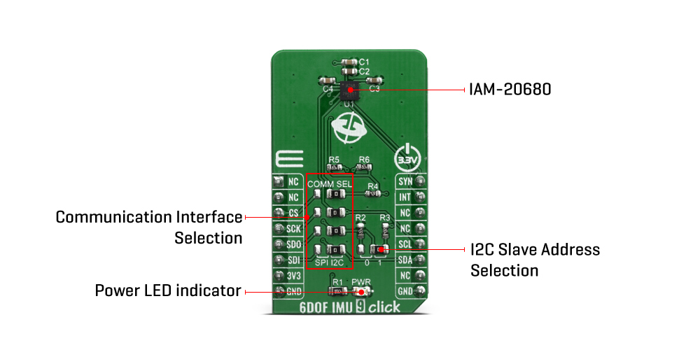
The 6DOF IMU 9 Click is a Click board™ which features the IAM-20680, a 6-axis MotionTracking device that combines a 3-axis gyroscope and a 3-axis accelerometer, from TDK InvenSense. A combination of the two most commonly used motion sensors allows for full 6D sensing. Tailored towards the Industry 4.0 This Click board™ can be used for automotive applications and navigation systems aids for dead reckoning, lift gate motion detection, accurate location for vehicle to vehicle and infrastructure, 360º view camera stabilization, car alarm, telematics and insurance vehicle tracking.
The 6DOF IMU 9 click is supported by a mikroSDK compliant library, which includes functions that simplify software development. This Click board™ comes as a fully tested product, ready to be used on a system equipped with the mikroBUS™ socket.
This product is no longer in stock
Availability date:
OFF
| Company | Stock | Price |
|---|---|---|
The 6DOF IMU 9 click is based on the IAM-20680 is a 6-axis MotionTracking device for Automotive applications from TDK, that combines a 3-axis gyroscope and a 3-axis accelerometer in a small 3x3x0.75mm (16-pin LGA) package. It also features a 512- byte FIFO that can lower the traffic on the serial bus interface and reduce power consumption by allowing the system processor to burst read sensor data and then go into a low-power mode. IAM-20680, with its 6-axis integration, enables manufacturers to eliminate the costly and complex selection, qualification, and system level integration of discrete devices, guaranteeing optimal motion performance.
The IAM-20680 has many features including the Digital-output X-, Y-, and Z-axis angular rate sensors (gyroscopes) with a user-programmable full-scale range of ±250 dps, ±500 dps, ±1000 dps, and ±2000 dps and integrated 16-bit ADCs, Digital-output X-, Y-, and Z-axis accelerometer with a programmable full scale range of ±2g, ±4g, ±8g, and ±16g and integrated 16-bit ADCs and a User-programmable digital filters for gyroscope, accelerometer, and temperature sensor.
The IAM-20680 includes the following additional features such as minimal cross-axis sensitivity between the accelerometer and gyroscope axes, a 512-byte FIFO buffer enables the applications processor to read the data in bursts, with a digital-output temperature sensor and the MEMS structure hermetically sealed and bonded at wafer level.
The 6DOF IMU 9 communicates to a system processor using either a SPI or an I2C serial interface. The IAM-20680 contains a 512-byte FIFO register that is accessible via the Serial Interface. The FIFO configuration register determines which data are written into the FIFO. Possible choices include gyro data, accelerometer data, temperature readings, and FSYNC input. A FIFO counter keeps track of how many bytes of valid data are contained in the FIFO. The FIFO register supports burst reads. The interrupt function may be used to determine when new data are available. The IAM-20680 allows FIFO read in low-power accelerometer mode.
6DOF IMU 9 click supports both SPI and I2C communication interfaces, allowing it to be used with a wide range of different MCUs. The communication interface can be selected by moving SMD jumpers grouped under the COM SEL to an appropriate position (SPI or I2C). The slave I2C address can also be configured by an SMD jumper when the Click board™ is operated in the I2C mode an SMD jumper labeled as ADD LSB is used to set the least significant bit (LSB) of the I2C address.
Due to the IAM-20680, the 6DOF IMU 9 click can be used for automotive applications and navigation systems aids for dead reckoning, lift gate motion detection, accurate location for vehicle to vehicle and infrastructure, 360º view camera stabilization, car alarm, telematics and insurance vehicle tracking.
Type
Acceleration,Gyroscope,Motion
Applications
Automotive applications and navigation systems aids for dead reckoning, lift gate motion detection, accurate location for vehicle to vehicle and infrastructure, 360º view camera stabilization, car alarm, telematics and insurance vehicle tracking
On-board modules
IAM-20680, a 6-axis MotionTracking device that combines a 3-axis gyroscope and a 3-axis accelerometer, from TDK InvenSense
Key Features
512-byte FIFO buffer, MEMS structure hermetically sealed and bonded at wafer level, Digital-output temperature sensor
Interface
I2C,SPI
Feature
No ClickID
Compatibility
mikroBUS™
Click board size
M (42.9 x 25.4 mm)
Input Voltage
3.3V
This table shows how the pinout on 6DOF IMU 9 click corresponds to the pinout on the mikroBUS™ socket (the latter shown in the two middle columns).
| Notes | Pin | Pin | Notes | ||||
|---|---|---|---|---|---|---|---|
| NC | 1 | AN | PWM | 16 | SYN | External sync | |
| NC | 2 | RST | INT | 15 | INT | Interrupt | |
| SPI Chip Select | CS | 3 | CS | RX | 14 | NC | |
| SPI Clock | SCK | 4 | SCK | TX | 13 | NC | |
| SPI Data OUT | SDO | 5 | MISO | SCL | 12 | SCL | I2C Clock |
| SPI Data IN | SDI | 6 | MOSI | SDA | 11 | SDA | I2C Data |
| Power Supply | 3.3V | 7 | 3.3V | 5V | 10 | NC | |
| Ground | GND | 8 | GND | GND | 9 | GND | Ground |
| Label | Name | Default | Description |
|---|---|---|---|
| LD1 | PWR | - | Power LED Indicator |
| JP1-JP4 | COM SEL | Right | Communication interface selection: left position SPI, right position I2C |
| JP5 | ADD LSB | Right | Save I2C address LSB selection: left position 0, right position 1 |
We provide a library for the 6DOF IMU 9 Click on our LibStock page, as well as a demo application (example), developed using MikroElektronika compilers. The demo can run on all the main MikroElektronika development boards.
Library Description
The library covers all the necessary functions to control 6DOF IMU 9 click board. Library performs a standard I2C or SPI interface communication.
Key functions:
void c6dofimu9_get_accel_data( int16_t *p_accel_x, int16_t *p_accel_y, int16_t *p_accel_z ) - Read Accel X-axis, Y-axis and Z-axis axis function.void c6dofimu9_get_gyro_data( int16_t *p_gyro_x, int16_t *p_gyro_y, int16_t *p_gyro_z ) - Read Gyro X-axis, Y-axis and Z-axis axis function.Examples description
The application is composed of three sections :
void application_task( )
{
    c6dofimu9_get_accel_data( &accel_axis_x, &accel_axis_y, &accel_axis_z );
    Delay_10ms( );
    c6dofimu9_get_gyro_data( &gyro_axis_x,  &gyro_axis_y, &gyro_axis_z );
    Delay_10ms( );

    mikrobus_logWrite( " Accel X :", _LOG_TEXT );
    IntToStr( accel_axis_x, logText );
    mikrobus_logWrite( logText, _LOG_TEXT );
    mikrobus_logWrite( "  |  ", _LOG_TEXT );
    mikrobus_logWrite( " Gyro X :", _LOG_TEXT );
    IntToStr( gyro_axis_x, logText );
    mikrobus_logWrite( logText, _LOG_LINE );

    mikrobus_logWrite( " Accel Y :", _LOG_TEXT );
    IntToStr( accel_axis_y, logText );
    mikrobus_logWrite( logText, _LOG_TEXT );
    mikrobus_logWrite( "  |  ", _LOG_TEXT );
    mikrobus_logWrite( " Gyro Y :", _LOG_TEXT );
    IntToStr( gyro_axis_y, logText );
    mikrobus_logWrite( logText, _LOG_LINE );

    mikrobus_logWrite( " Accel Z :", _LOG_TEXT );
    IntToStr( accel_axis_z, logText );
    mikrobus_logWrite( logText, _LOG_TEXT );
    mikrobus_logWrite( "  |  ", _LOG_TEXT );
    mikrobus_logWrite( " Gyro Z :", _LOG_TEXT );
    IntToStr( gyro_axis_z, logText );
    mikrobus_logWrite( logText, _LOG_LINE );

    mikrobus_logWrite( "-------------------------------------", _LOG_LINE );
    Delay_1sec( );
}
The full application code, and ready to use projects can be found on our LibStock page.
Other mikroE Libraries used in the example:
Additional notes and informations
Depending on the development board you are using, you may need USB UART click, USB UART 2 click or RS232 click to connect to your PC, for development systems with no UART to USB interface available on the board. The terminal available in all MikroElektronika compilers, or any other terminal application of your choice, can be used to read the message.
This Click board™ is supported with mikroSDK - MikroElektronika Software Development Kit. To ensure proper operation of mikroSDK compliant Click board™ demo applications, mikroSDK should be downloaded from the LibStock and installed for the compiler you are using.
For more information about mikroSDK, visit the official page.
NOTE: Please be advised that any peripheral devices or accessories shown connected to the Click board™ are not included in the package. Check their availability in our shop or in the YMAN section below.

$889.00

$95.00

$549.00

$299.00

$29.00

$29.00

$3.30

$3.60

$119.00

$449.00

$349.00

$349.00

$349.00

$299.00

$269.00

$249.00

$209.00
