


OFF
GO LOCAL
| Company | Stock | Price |
|---|---|---|


MIKROE-4228
17 g
Status:
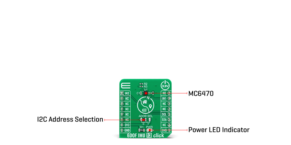
6DOF IMU 13 Click is a compact add-on board that contains an eCompass that consists of a 3-axis linear accelerometer and a 3-axis magnetic field sensor. This board features the MC6470, an accelerometer and magnetometer for a 6 DoF (6 Degrees of Freedom) sensor solution, from MEMSIC. It has a linear acceleration full-scale range of ±16g and a low noise magnetic sensor with up to 0.15μT magnetic field resolution, with a single I2C interface available to separately control magnetometer and accelerometer functions, enabling independent operation of functions for application flexibility. This Click board™ is an excellent choice for applications where there is a need for high-precision directional pointing such as map orientation, virtual reality data overlay, enhanced navigation, and gyroscope replacement.
6DOF IMU 13 Click is supported by a mikroSDK compliant library, which includes functions that simplify software development. This Click board™ comes as a fully tested product, ready to be used on a system equipped with the mikroBUS™ socket.
This product is no longer in stock
Availability date:
OFF
| Company | Stock | Price |
|---|---|---|
6DOF IMU 13 Click is based on the MC6470 that combines an accelerometer and magnetometer for a 6 DoF (6 Degrees of Freedom) sensor solution, from mCube Inc. An accelerometer has two states of operation: STANDBY which is his default state after Power-Up function, and WAKE. The STANDBY state offers the lowest power consumption, and only in this state, the I2C interface is active and all register reads and writes are allowed. There is no event detection, sampling, or acceleration measurement in this state. In WAKE state, the only write access is permitted to the MODE register. The full-scale acceleration range can be adjusted from ±2g, up to ±16g with a 14-bit resolution.
This Click Board™ also includes a high-performance magnetic sensor with 0.15μT resolution, broad field range up to ±2.4mT, and a programmable output data rate from 0.5 to 100 Hz. The magnetometer has two operational modes, Stand-By and Active Mode with Force and Normal State, whose primary purpose is for power management. It also provides additional functions such as Data Ready Function which occurs when new measured results are updated, Offset Calibration and Drift Functions, and Temperature Measurement Function that retrieves temperature data used for internal compensation of output data from an internal temperature sensor. The magnetic sensor output value of each axis is positive when turned toward the magnetic north.
The MC6470 possesses two interrupt outputs, magnetometer (IN2) and an accelerometer (IN1) interrupts, routed to the AN and INT pins on the mikroBUS™ used to signal MCU that an event has been sensed. It also supports directional tap detection in ±X, ±Y, or ±Z axis, where each axis is independent, although only one direction per axis is supported simultaneously. In this case, the interrupt pins can be used to indicate that a tap event has been detected.
6DOF IMU 13 Click communicates with MCU using the standard I2C 2-Wire interface with a maximum frequency of 400kHz. The MC6470 always operates as an I2C slave device on both magnetometer and accelerometer I2C interfaces and allows the choice of the least significant bit (LSB) of its I2C slave address which can be done by using the SMD jumper labeled as ADDR SEL.
This Click Board™ is designed to be operated only with a 3.3V logic level. A proper logic voltage level conversion should be performed before the Click board™ is used with MCUs with different logic levels.
Type
Acceleration,Magnetic,Motion
Applications
Can be used for applications where there is a need for high-precision directional pointing such as map orientation, virtual reality data overlay, enhanced navigation, and gyroscope replacement.
On-board modules
6DOF IMU 13 Click is based on the MC6470, 6 DoF solution, a 3-axis accelerometer, and 3-axis magnetometer sensors, from mCube Inc.
Key Features
Low power consumption, high precision, programmable interrupts, user scalable accel full-scale range, programmable output data rate, and more.
Interface
I2C
Feature
No ClickID
Compatibility
mikroBUS™
Click board size
S (28.6 x 25.4 mm)
Input Voltage
3.3V
This table shows how the pinout on 6DOF IMU 13 Click corresponds to the pinout on the mikroBUS™ socket (the latter shown in the two middle columns).
| Notes | Pin | Pin | Notes | ||||
|---|---|---|---|---|---|---|---|
| Magnet. Interrupt | IN2 | 1 | AN | PWM | 16 | NC | |
| NC | 2 | RST | INT | 15 | IN1 | Accel. Interrupt | |
| NC | 3 | CS | RX | 14 | NC | ||
| NC | 4 | SCK | TX | 13 | NC | ||
| NC | 5 | MISO | SCL | 12 | SCL | I2C Clock | |
| NC | 6 | MOSI | SDA | 11 | SDA | I2C Data | |
| Power Supply | 3.3V | 7 | 3.3V | 5V | 10 | NC | |
| Ground | GND | 8 | GND | GND | 9 | GND | Ground |
| Label | Name | Default | Description |
|---|---|---|---|
| LD1 | PWR | - | Power LED Indicator |
| JP1 | ADDR SEL | Left | I2C Address Selection: Left position 0, Right position 1 |
| Description | Min | Typ | Max | Unit |
|---|---|---|---|---|
| Supply Voltage | -0.3 | 3.3 | 3.6 | V |
| Acceleration (any axis) | - | - | 10.000 | g |
| Acceleration Sensitivity | 8 | - | 4096 | LSB/g |
| Magnetometer Field Range | -2.4 | - | 2.4 | mT |
| Magnetometer Sensitivity | - | 0.15 | - | µT / LSB |
| Operating Temperature Range | -40 | - | +85 | °C |
We provide a library for the 6DOF IMU 13 Click on our LibStock page, as well as a demo application (example), developed using MikroElektronika compilers. The demo can run on all the main MikroElektronika development boards.
Library Description
The library covers all the necessary functions that enables the usage of the 6DOF IMU 13 Click board. It initializes and defines the I2C bus driver and drivers that offer a plethora of settings. The library also offers functions that allow reading of accelerometer and magnetometer, as well as generic read and write function that offer reading( and writing) of different lenghts of data.
Key functions:
void c6dofimu13_get_magneto ( float *mag_x, float *mag_y, float *mag_z ); - Function is used to read magnetometer data.void c6dofimu13_get_accel ( float *accel_x, float *accel_y, float *accel_z ); - Function is used to get acceleration rate.void c6dofimu13_accel_init ( uint8_t samp_rate, uint8_t samp_range, uint8_t samp_res ); - Function is used to initialize accelerometer, user can select data rate, range and resolution.Examples description
The application is composed of three sections :
void application_task ( )
{
    mikrobus_logWrite( "-----------------------", _LOG_LINE );
    mikrobus_logWrite( " Magnetometer readings ", _LOG_LINE );
    c6dofimu13_get_magneto ( &mag_x, &mag_y, &mag_z );

    FloatToStr( mag_x, log_txt );
    mikrobus_logWrite( "X-axis :", _LOG_TEXT );
    mikrobus_logWrite( log_txt, _LOG_TEXT );
    mikrobus_logWrite( "µT", _LOG_LINE );

    FloatToStr( mag_y, log_txt );
    mikrobus_logWrite( "Y-axis :", _LOG_TEXT );
    mikrobus_logWrite( log_txt, _LOG_TEXT );
    mikrobus_logWrite( "µT", _LOG_LINE );

    FloatToStr( mag_z, log_txt );
    mikrobus_logWrite( "Z-axis :", _LOG_TEXT );
    mikrobus_logWrite( log_txt, _LOG_TEXT );
    mikrobus_logWrite( "µT", _LOG_LINE );

    mikrobus_logWrite( "-----------------------", _LOG_LINE );
    Delay_ms( 500 );

    mikrobus_logWrite( " Accelerometer readings ", _LOG_LINE );
    c6dofimu13_get_accel( &acc_x, &acc_y, &acc_z );

    FloatToStr( acc_x, log_txt );
    mikrobus_logWrite( "X-axis :", _LOG_TEXT );
    mikrobus_logWrite( log_txt, _LOG_TEXT );
    mikrobus_logWrite( "g", _LOG_LINE );

    FloatToStr( acc_y, log_txt );
    mikrobus_logWrite( "Y-axis :", _LOG_TEXT );
    mikrobus_logWrite( log_txt, _LOG_TEXT );
    mikrobus_logWrite( "g", _LOG_LINE );

    FloatToStr( acc_z, log_txt );
    mikrobus_logWrite( "Z-axis :", _LOG_TEXT );
    mikrobus_logWrite( log_txt, _LOG_TEXT );
    mikrobus_logWrite( "g", _LOG_LINE );

    mikrobus_logWrite( "-----------------------", _LOG_LINE );
    Delay_ms( 1000 );
}
The full application code, and ready to use projects can be found on our LibStock page.
Other mikroE Libraries used in the example:
Additional notes and informations
Depending on the development board you are using, you may need USB UART click, USB UART 2 click or RS232 click to connect to your PC, for development systems with no UART to USB interface available on the board. The terminal available in all MikroElektronika compilers, or any other terminal application of your choice, can be used to read the message.
This Click board™ is supported with mikroSDK - MikroElektronika Software Development Kit. To ensure proper operation of mikroSDK compliant Click board™ demo applications, mikroSDK should be downloaded from the LibStock and installed for the compiler you are using.
For more information about mikroSDK, visit the official page.
NOTE: Please be advised that any peripheral devices or accessories shown connected to the Click board™ are not included in the package. Check their availability in our shop or in the YMAN section below.

$889.00

$95.00

$549.00

$299.00

$29.00

$29.00

$3.30

$3.60

$119.00

$449.00

$349.00

$349.00

$349.00

$299.00

$269.00

$249.00

$209.00
