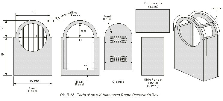
For all lovers of the electronics, the box where their device is to be put is the famous “production weak link”. The finished boxes are either impossible to purchase, or they can be bought but their dimensions or shape is inappropriate, or they are too expensive, or... In cases like this one should be quick-witted enough to find some square-shaped box that is being used at household, or some packaging box or similar. That is how it’s done in the “whole white world”. Two years ago, in the famous electrotechnical magazine ETI TOP PROJECTS the article named “TIC TAC RADIO” was printed, where a receiver with ZN414 that is placed in the transparent plastic box of TIC TAC mints (In the abstract, it was written that making this device serves well as an excuse for buying candies, which is probably meant for the readers that are on a diet for aesthetic reasons).However, the “finishing touch” is of great importance for everything. The majority of your friends will be more impressed by a lovely box where the receiver is placed, than the reproduction quality, type of modulation and other technical characteristics. And a nice, appropriate box cannot be bought, it is up to you to make it. It can be something as on pic.3.11 or similar. The idea can be also found in some catalogue of radio receivers’ manufacturers, or you can think of something of your own. As far as the author of these lines is concerned, he likes best the wooden boxes from the 20’s and 30’s of the previous century, from the times of the charleston, E. H. Armstrong and Al Capone. They looked something like those on the pic.5.17 and can serve you as an inspiration for your personal design.The mid button is for the variable capacitor for station tuning, the right one is for the potentiometer for volume regulation. The button on the left can be a rotary switch for turning on/off (S). It can also be a tone regulation button, and for the reaction-type receivers it can be a button of the potentiometer that regulates the magnitude of the reaction. In the last two cases, the on/off switch (S) is located on the regulation potentiometer. The outside antenna and ground hubs are located at the rear panel of the box. The wires connecting the hubs with the PCB should be isolated, flexible and long enough to be able to open the panel and put it at upright position.If the receiver is power supplied from the outside net, a green LED should also be added, as the power indicator. The good place for it is just above the variable capacitor’s button, instead of the triangle-shaped marker. Pic.5.18 shows the parts for the first box from pic.5.17. For the front and rear side two pieces of 5 cm thick plywood, measuring 22 cm x 15 cm are needed; for the side panels, two pieces of 10 cm thick plywood, 15 cm x 9 cm, and for the bottom side - one piece of 10 cm thick plywood, measuring 13 cm x 9 cm. The best way to cut these parts is to be done by the carpenter on the special machine, since only then will they be of strictly rectangular shape, and bottom and side panels will have exactly the same width, which is very important during assembling. On the front side, the circle and the arc are drawn with the aid of the sector, and the cutting is done with the carving saw. The part that is cut from the back panel will serve as a closure. When it is cut it isn’t necessary to treat it with emery, since it will fit nicely in the hole on the rear panel even if it isn’t cut evenly. On the inner side of the rear panel two plywood lattices measuring about 2 cm x 13 cm should be nailed. Four wood screws will be screwed in them later (the holes are shown as four dots), which will serve to tighten the closure. Connecting of the pieces is done with the wood glue and small nails. Before you start hammering, it is very useful to drill a few holes for the nails in the front and rear panel with 1 mm drill. The nails are partially hammered into the panels, the edges are then covered with glue, and the nailing can then be done. When all this is finished, the box should look as the drawing at the right end art of the pic.5.18 *vertical stripes over the loudspeaker opening are not shown. They can be omitted, and you can nail in a few thin lattices, when the box is finished, as shown on the last drawing on the pic.5.17). The semicircle part is made of 5 mm x 5 mm lattices, or similar, which are put side by side on the upper edges of the front and rear panels, that are covered with glue (the picture shows only one of these lattices). When the last one is fitted, the space between them is filled with “putty” that is made by mixing the fine wooden chips with the wood glue, with the aid of a steel plate. After that, the lattices are tightened to the panels’ edges by two pieces of strong scotch tape, which are shown in dashed lines, and everything is left to dry well. When drying is, after about 10 hours, finished, all the edges and lattice parts that protrude are well flattened with emery. All the remaining holes are filled with the fast-drying putty, and everything is abraded once again, and the putty is applied again, and abraded again, etc., until the upper part is semicircle-shaped, all the sides smooth and the edges correct.* Before the loudspeaker is attached with screws, a piece of decorating cloth should be placed between the panel and the loudspeaker, which will protect it and contribute to better looking box.* Perhaps some of the readers will seem that there’s a lot of exaggeration in previous lines, and even too much pedantry. There’s a Latin proverb, that says: AGE QUOD AGIS - Do the things you do, which, in our case, can be interpreted as: You should either make the box properly or not making it at all.* This box is relatively small, it is predicted for the loudspeaker that is about 12 cm wide. If you have bigger loudspeaker, and it will certainly play both louder and better, you should make a bigger box. The dimensions calculation is done by dividing the diameter of the bigger opening, that will suit bigger loudspeaker, in centimetres, by 11, and all the measures on pic.5.18 are multiplied with the number attained. E.g. if the diameter for the new, bigger hole is 15 cm, new dimensions are obtained by multiplying the old ones by 1.36.


 * Before the loudspeaker is attached with screws, a piece of decorating cloth should be placed between the panel and the loudspeaker, which will protect it and contribute to better looking box.
* Perhaps some of the readers will seem that there’s a lot of exaggeration in previous lines, and even too much pedantry. There’s a Latin proverb, that says: AGE QUOD AGIS - Do the things you do, which, in our case, can be interpreted as: You should either make the box properly or not making it at all.
* This box is relatively small, it is predicted for the loudspeaker that is about 12 cm wide. If you have bigger loudspeaker, and it will certainly play both louder and better, you should make a bigger box. The dimensions calculation is done by dividing the diameter of the bigger opening, that will suit bigger loudspeaker, in centimetres, by 11, and all the measures on pic.5.18 are multiplied with the number attained. E.g. if the diameter for the new, bigger hole is 15 cm, new dimensions are obtained by multiplying the old ones by 1.36.
* Before the loudspeaker is attached with screws, a piece of decorating cloth should be placed between the panel and the loudspeaker, which will protect it and contribute to better looking box.
* Perhaps some of the readers will seem that there’s a lot of exaggeration in previous lines, and even too much pedantry. There’s a Latin proverb, that says: AGE QUOD AGIS - Do the things you do, which, in our case, can be interpreted as: You should either make the box properly or not making it at all.
* This box is relatively small, it is predicted for the loudspeaker that is about 12 cm wide. If you have bigger loudspeaker, and it will certainly play both louder and better, you should make a bigger box. The dimensions calculation is done by dividing the diameter of the bigger opening, that will suit bigger loudspeaker, in centimetres, by 11, and all the measures on pic.5.18 are multiplied with the number attained. E.g. if the diameter for the new, bigger hole is 15 cm, new dimensions are obtained by multiplying the old ones by 1.36.