


OFF
GO LOCAL
| Company | Stock | Price |
|---|---|---|


MIKROE-2550
18 g
Status:
Manometer 2 click carries the 5525DSO-SB001GS digital pressure sensor, based on leading MEMS technology from TE Connectivity. The click is designed to run on a 3.3V power supply. It communicates with the target microcontroller over I2C or SPI interface.
This product is no longer in stock
Availability date:
OFF
| Company | Stock | Price |
|---|---|---|
Manometer 2 click carries the 5525DSO-SB001GS digital pressure sensor, based on leading MEMS technology. The click is designed to run on a 3.3V power supply. It communicates with the target microcontroller over I2C or SPI interface.
The 5525DSO-SB001GS is a new generation of Digital Small Outline pressure sensors with SPI and I2C bus interface designed for high volume OEM users.
The sensor module includes a pressure sensor and an ultra-low power 24-bit ∆Σ ADC with internal factory calibrated coefficients. It provides a 24-bit digital pressure and temperature value and different operation modes that allow the user to optimize for conversion speed and current consumption.
The 5525DSO-SB001GS consists of a piezo-resistive sensor and a sensor interface IC. The main function of the MS5525DSO is to convert the uncompensated analog output voltage from the piezo-resistive pressure sensor to a 24-bit digital value, as well as providing a 24-bit digital value for the temperature of the sensor.
Manometer 2 click measures absolute pressure of 1PSI max, trough the barbed port.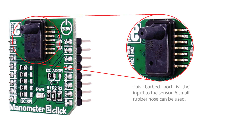
You can choose between SPI and I2C communication.
Type
Pressure
Applications
Factory automation, altitude and airspeed measurements, medical instruments, leak detection, etc.
On-board modules
MS5525DSO digital pressure sensor
Key Features
sensor module includes a pressure sensor and an ultra-low power 24-bit ∆Σ ADC with internal factory calibrated coefficients
Interface
I2C,SPI
Feature
No ClickID
Compatibility
mikroBUS™
Click board size
S (28.6 x 25.4 mm)
Input Voltage
3.3V
This table shows how the pinout on Manometer 2 click corresponds to the pinout on the mikroBUS™ socket (the latter shown in the two middle columns).
| Notes | Pin | Pin | Notes | ||||
|---|---|---|---|---|---|---|---|
| NC | 1 | AN | PWM | 16 | NC | ||
| NC | 2 | RST | INT | 15 | NC | ||
| Chip Select | CS | 3 | CS | TX | 14 | NC | |
| SPI Clock | SCK | 4 | SCK | RX | 13 | NC | |
| SPI Master Input Slave Output | MISO | 5 | MISO | SCL | 12 | SCL | I2C Clock |
| SPI Master Output Slave Input | MOSI | 6 | MOSI | SDA | 11 | SDA | I2C Data |
| Power supply | +3.3V | 7 | 3.3V | 5V | 10 | NC | |
| Ground | GND | 8 | GND | GND | 9 | GND | Ground |
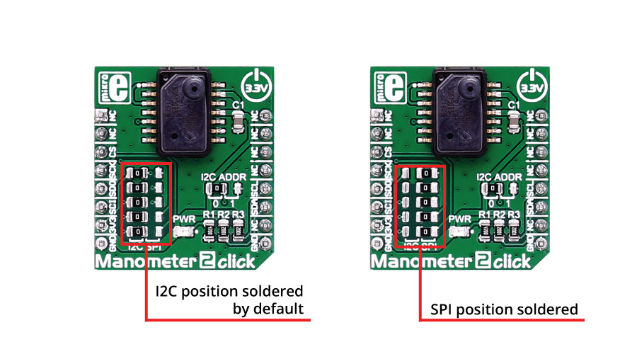
In order to set the SPI interface, you need to move all the 5 jumpers (JP1-JP5).
These jumpers are soldered in I2C interface position by default.
There is an option to select the alternate address with jumper J6 in the case of I2C interface (default position is logic 0).
Code examples for Manometer 2 click, written for MikroElektronika hardware and compilers are available on Libstock.
The following code snippet shows the Manometer 2 click example, which takes care of initializing peripherals and the device, and then outputs the current pressure and temperature every 2 seconds.
01 void systemInit()
02 {
03     UART1_Init(9600);
04     Delay_ms(100);
05     UART1_Write_Text("nrInitialization...nr");
06     I2C1_Init_Advanced(100000, &_GPIO_MODULE_I2C1_PB67);
07     Delay_ms(100);
08     MMETER2_initDriver(pp001GS ,I2CAddress, I2C1_Start, I2C1_Write, I2C1_Read);
09
10 }
11
12 void main()
13 {
14     char uartText [60];
15     float measureResult;
16     systemInit();
17     UART1_Write_Text("Initializednr");
18
19    while( 1 )
20     {
21         measureResult = MMETER2_getTemperature(CONVERT_4096);
22         sprintf(uartText, "Temperature is: %3.3f Celsiusrn", measureResult);
23         UART1_Write_Text(uartText);
24
25        measureResult = MMETER2_getPressure(CONVERT_4096);
26         sprintf(uartText, "Pressure is:    %3.3f PSIrnrn", measureResult);
27         UART1_Write_Text(uartText);
28
29        Delay_ms( 2000 );
30     }
31
32 }
NOTE: Please be advised that any peripheral devices or accessories shown connected to the Click board™ are not included in the package. Check their availability in our shop or in the YMAN section below.

$889.00

$95.00

$549.00

$299.00

$29.00

$29.00

$6.59

$3.60

$119.00

$449.00

$349.00

$349.00

$349.00

$299.00

$269.00

$249.00

$209.00
