


OFF

MIKROE-3692
23 g
Status:
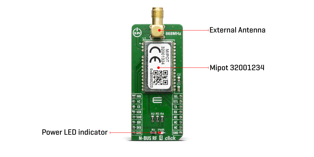
M-BUS RF 4 Click is a mikroBUS™ add-on board with a MIPOT 32001324 RF wireless transceiver. This module operates in the 868 MHz SRD Band. Thanks to its small LCC form factor (15 x 25 mm only) and its low power consumption this module allows the implementation of highly integrated low power (battery operated) solutions for water, gas, heat or electricity metering applications, both on meter or concentrator devices.
The M-BUS RF 4 click is supported by a mikroSDK compliant library, which includes functions that simplify software development. This Click board™ comes as a fully tested product, ready to be used on a system equipped with the mikroBUS™ socket.
This product is no longer in stock
Availability date:
Considering that wireless M-Bus is designed to be a robust, power efficient, long range wireless communication solution that operates in the license-free ISM bands that makes him one of the most ideal industrial protocols.
M-BUS RF 4 click is a mikroBUS™ add-on board with a 32001324 – 868MHz band TRX module from Mipot. The radio operates at the unlicensed 868 MHz SRD frequency band and has specified serial data rates of up to 115.2 Kbps. This M-BUS RF 4 click is ideal for developing various applications, mainly solutions for water or gas, as well as heat and electricity metering applications, and even on meter and concetrator devices. The module supports various operating modes (S, T, R, C) to meet the requirements of one-way and two-way data communication, in stationary and mobile systems. The embedded stack implemented according to EN13757-4 Standard provides the physical access to the Wireless M-Bus communication.
At startup time, the Module reads INTERFACE_SELECTION input pin state, which is routed to the PWM pin (marked SEL on Click board) of the mikroBUS™ socket. This pin should be left unconnected or set to high state to select the UART interface or set to low state to select the SPI interface for communicating with the main MCU. Widely used SPI and UART interfaces allow integration flexibility and easy development of customer products. The module meets all the requirements in the industrial temperature range -40/+85°C. Besides that, the module is also certified according to R&TTED 1999/05/EC and is compliant with the ReACH And ROHS directives.
The embedded stack implemented in the module according to EN13757-4 Standard provides the physical access to the Wireless M-Bus communication. M-BUS RF 4 click communicates with the target MCU through the mikroBUS™ UART or SPI interface, with additional functionality provided by IND, SEL, and RTS CS/CTS pins.
This Click Board™ is designed to be operated only with 3.3V logic level. A proper logic voltage level conversion should be performed before the Click board™ is used with MCUs with logic levels of 5V.
Type
Sub-1 GHz Transceievers
Applications
Wireless M-BUS RF 4 click was designed for gas and water meter, heat or electricity applications
On-board modules
MIPOT 32001324 RF wireless transceiver
Key Features
Data rates: 115.2 Kbps serial
Interface
SPI,UART
Feature
No ClickID
Compatibility
mikroBUS™
Click board size
M (42.9 x 25.4 mm)
Input Voltage
3.3V
This table shows how the pinout on the M-BUS RF 4 click corresponds to the pinout on the mikroBUS™ socket (the latter shown in the two middle columns).
| Notes | Pin | Pin | Notes | ||||
|---|---|---|---|---|---|---|---|
| Data Indicate | IND | 1 | AN | PWM | 16 | SEL | Communication Selection In |
| NC | 2 | RST | INT | 15 | RTS | UART RTS | |
| Chip Select | CS | 3 | CS | RX | 14 | TX | UART TX |
| Serial Clock | SCK | 4 | SCK | TX | 13 | RX | UART RX |
| SPI Data Out | SDO | 5 | MISO | SCL | 12 | NC | |
| SPI Data In | SDI | 6 | MOSI | SDA | 11 | NC | |
| Power Supply | 3.3V | 7 | 3.3V | 5V | 10 | NC | |
| Ground | GND | 8 | GND | GND | 9 | GND | Ground |
| Label | Name | Default | Description |
|---|---|---|---|
| LD1 | PWR | - | Power LED Indicator |
We provide a library for the M-BUS RF 4 click on our LibStock page, as well as a demo application (example), developed using MikroElektronika compilers. The demo can run on all the main MikroElektronika development boards.
Library Description
The library provides the functions of sending commands and receiving data using UART communication. For additional commands and their form - and the number of parameters to be sent, look at the datasheet.
Key functions:
void mbusrf4_sendCommand( uint8_t command, uint8_t length, uint8_t *payloadBuff) - Send command - UART communicationvoid mbusrf4_setCommunicationMode(uint8_t mode) - Set communication SPI/UARTExamples description
The application is composed of three sections :
void applicationTask()
{
    /* RX App mode */
    if(fDataResp == 1 && _appMode == _MBUSRF4_USER_APP_RX_MODE)
    {
       mikrobus_logWrite ( " ----- NEW - RX DATA ---- ", _LOG_LINE );
       _display_rxBuffer( 20 );
       mikrobus_logWrite ( " ------------------------ ", _LOG_LINE );
       fDataResp = 0;
    }

    /* TX App Mode */
    if(_appMode == _MBUSRF4_USER_APP_TX_MODE)
    {
        mbusrf4_sendCommand( _MBUSRF4_CMD_TX_MSG, 18, &txBuffer[0] );
        mikrobus_logWrite ( " --- SEND - TX BUFFER --- ", _LOG_LINE );
        _display_rxBuffer( 5 );
        mikrobus_logWrite ( " ------------------------ ", _LOG_LINE );

        Delay_ms( 1500 );
    }
}
Additional Functions :
The full application code, and ready to use projects can be found on our LibStock page.
Other mikroE Libraries used in the example:
Additional notes and informations
Depending on the development board you are using, you may need USB UART click, USB UART 2 click or RS232 click to connect to your PC, for development systems with no UART to USB interface available on the board. The terminal available in all MikroElektronika compilers, or any other terminal application of your choice, can be used to read the message.
This Click board™ is supported with mikroSDK - MikroElektronika Software Development Kit. To ensure proper operation of mikroSDK compliant Click board™ demo applications, mikroSDK should be downloaded from the LibStock and installed for the compiler you are using.
For more information about mikroSDK, visit the official page.
NOTE: Please be advised that any peripheral devices or accessories shown connected to the Click board™ are not included in the package. Check their availability in our shop or in the YMAN section below.

$889.00

$95.00

$549.00

$299.00

$29.00

$29.00

$6.59

$3.60

$119.00

$449.00

$349.00

$349.00

$349.00

$299.00

$269.00

$249.00

$146.30
