


OFF
GO LOCAL
| Company | Stock | Price |
|---|---|---|


MIKROE-2807
20 g
Status:
LED driver 2 click carries the MCP1643 - LED constant current regulator, made by Microchip. It is a compact, high-efficiency, fixed frequency, synchronous step-up converter, optimized to drive one LED with the constant current. It can be powered by a two-cell alkaline/NiMH/NiCd battery (2.4V), or via the mikroBUS™ power supply pins. LED Driver 2 click also features 3W high power LED by QT-Brightek. This LED can be dimmed by applying the variable duty cycle PWM signal to the EN pin of the MCP1643 regulator, through the PWM pin of the mikroBUS™.
Thanks to its relatively high constant current driving capability and the overvoltage protection on the output, this integrated circuit is perfectly suited for high brightness/power LED applications: portable LED lighting products, LED Flashlight and Head Lamps, Rechargeable Flashlights, General LED constant current applications and so on.
This product is no longer in stock
Availability date:
OFF
| Company | Stock | Price |
|---|---|---|
LED driver 2 click carries the MCP1643 - LED constant current regulator, made by Microchip. It is a compact, high-efficiency, fixed frequency, synchronous step-up converter, optimized to drive one LED with the constant current. It can be powered by a two-cell alkaline/NiMH/NiCd battery (2.4V), or via the mikroBUS™ power supply pins. LED Driver 2 click also features 3W High brightness LED by QT-Brightek. This LED can be dimmed by applying the variable duty cycle PWM signal to the EN pin of the MCP1643 regulator, through the PWM pin of the mikroBUS™.
Thanks to its relatively high constant current driving capability and the overvoltage protection on the output, this integrated circuit is perfectly suited for high brightness/power LED applications: portable LED lighting products, LED Flashlight and Head Lamps, Rechargeable Flashlights, General LED constant current applications and so on.
MCP1643 is basically a boost regulator with a low voltage reference of 120mV (VFB). The main feature of the regulator is that it is optimized to keep the current running through the LED - constant, by regulating the voltage across the feedback resistor. The VFB pin is used to regulate the voltage across the feedback resistor to 120 mV, keeping the output LED current regulated. As feedback resistor (R2 on the provided schematic) is connected to the FB pin and its resistance is 0.4Ω, the maximum current through the LED can easily be calculated by using the following formula: ILED = VFB/R2 = 120mV/0.4Ω = 300mA.
The voltage drop on the feedback resistor has to be low, in order to avoid dissipation. In the case of MCP1643, this voltage is set to 120mV which ensures no dissipation issues at all.
The onboard VIN SEL SMD jumper offers the selection of the input voltage source: it can be set to use a two-cell NiMH battery connected to VIN terminal (2.4V), or the power supply pin from the mikroBUS™. The voltage from the mikroBUS™ can be set with the VCCIO SMD jumper to either 5V or 3.3V. Since the forward voltage on the high power LED is 3.2V, the click board comes equipped with the MCP1826, an LDO regulator by Microchip, which is used to drop the selected mikroBUS™ voltage down to around 2.4V so that the MPC1643 input voltage requirements are met.
High brightness 3W LED is already attached to the output of the MCP1643 and it comes soldered on the board, so the circuit is ready to be used right away.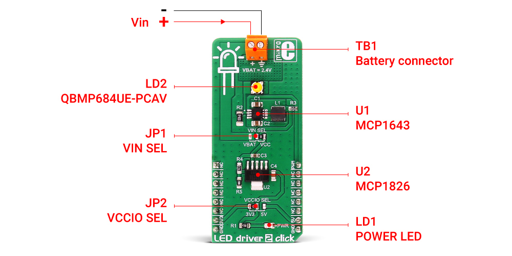
The LED brightness can be regulated by applying a variable duty cycle PWM signal to the EN pin of the MCP1643 regulator (routed to PWM pin on the mikroBUS™). This results in changing the current running through the LED in a linear fashion, from 0 to the value set by the resistor, depending on the PWM cycle.
The device also features an output overvoltage protection that limits the output voltage to 5.0V typical, in case the LED fails or output load is disconnected. Also, the device features a thermal shutdown at +150°C with a hysteresis of +25°C and the overcurrent protection that prevents failures due to short circuits on the output.
Type
LED Drivers
Applications
LED Driver 2 click is an ideal solution for a reliable and efficient driving of a single or multi-stream LED arrays, including monochrome LED, white LED, and IR LED arrays, providing up to 28V at the output
On-board modules
MCP1643 - 1 MHz Low Start-up Voltage Synchronous Boost LED Constant Current Regulator, from Microchip
Key Features
1.6A typical peak input current limit, up to 550 mA LED load current, overvoltage Protection, inrush current limiting
Interface
GPIO
Feature
No ClickID
Compatibility
mikroBUS™
Click board size
L (57.15 x 25.4 mm)
Input Voltage
3.3V or 5V
This table shows how the pinout on LED driver 2 click corresponds to the pinout on the mikroBUS™ socket (the latter shown in the two middle columns).
| Notes | Pin | Pin | Notes | ||||
|---|---|---|---|---|---|---|---|
| NC | 1 | AN | PWM | 16 | PWM | MCP1643 Enable | |
| NC | 2 | RST | INT | 15 | NC | ||
| NC | 3 | CS | RX | 14 | NC | ||
| NC | 4 | SCK | TX | 13 | NC | ||
| NC | 5 | MISO | SCL | 12 | NC | ||
| NC | 6 | MOSI | SDA | 11 | NC | ||
| Power supply | 3V3 | 7 | 3.3V | 5V | 10 | 5V | Power supply |
| Ground | GND | 8 | GND | GND | 9 | GND | Ground |
| Description | Min | Typ | Max | Unit |
|---|---|---|---|---|
| Battery supply voltage | 2.4 | V | ||
| High Brightness LED current | 0 | 300 | mA |
| Label | Name | Default | Description |
|---|---|---|---|
| JP1 | VIN SEL | Right | Power supply voltage selection, left position VBAT, right position VCC |
| JP2 | VCCIO SEL | Left | Power supply voltage selection, left position 3V3, right position 5V |
| TB1 | Screw terminal | - | Screw terminal for connecting the battery |
| LD1 | Power LED | - | Power LED indicates that the click is powered on |
| LD2 | High Brightness LED | - | High Brightness LED with regulated current |
We provide a demo application for the LED driver 2 click on our LibStock page, developed using MikroElektronika compilers. The demo can run on all the main MikroElektronika development boards with minimal change to the code depending on the microcontroller used.
Examples Description
The application is composed of three sections :
void LED_Driver_2_Task()
{
    dutyCycle += 50;
    PWM_Set_Duty(dutyCycle, 1);

    if (dutyCycle > pwmPeriod)
    {
        dutyCycle = 0;
    }
    Delay_ms(10);
}
The full application code, and ready to use projects can be found on our LibStock page.
Other mikroE Libraries used in the example:
NOTE: Please be advised that any peripheral devices or accessories shown connected to the Click board™ are not included in the package. Check their availability in our shop or in the YMAN section below.

$71.00

$30.00

$889.00

$83.00

$95.00

$549.00

$299.00

$29.00

$29.00

$6.59

$3.60

$119.00

$349.00

$349.00

$299.00

$449.00

$349.00

$269.00

$249.00

$209.00
