APPENDIX E Ladder diagram instructions (2/3)
E.21 HIGH-SPEED TIMER - Timer with 0.01s resolution
| Description |
This instruction is identical to the previous TIM instruction, except for the resolution of decrementing. In case of TIM instruction this interval equals 0.1s, while with TIMH instruction it equals 0.01s. Changing the condition to ON starts the countdown with 0.01s decrements from the predefined value down to zero. If the state of condition changes to OFF timer will be reset. Value of parameter SV (abbreviation for Set Value) is multiplied by 0.01 s resulting in total time in seconds. Value given in the middle part of the block is called TC number. Each TC number can be used for defining one couner or timer. It can take values from 000 - 127 range. Lower part of the block is reserved for displaying the starting value of timer. Word with this role can belong to sectors IR, AR, DM, HR, LR or can be given as a constant, with values from 00.00 - 99.9.9 range. If parameter SV is given as a constant, it is necessary to put character “#” ahead of value. |
| Ladder symbol |
 |
| Limitations |
The number of timer cannot be used for a counter or another timer. Value of SV must be in 00.00 - 99.99 range. Recommended range for a number of timer is 000 - 003. |
| Flag |
Affects the appropriate flag in TC area. |
| Example |
 Changing the state of condition bit IR000.00 to ON starts the countdown (in this case for 27*0.01s=0.27 seconds). After the passing of given period of time, the appropriate bit IM003 changes state to ON, thus fulfilling the condition for executing the instructions on the right (in this case bit IR010.01 changes state to ON). Condition bit must be constantly ON for a given time period for bit TIM002 to be set. If condition state changes to OFF during the given time period, timer resets and goes back to the beginning. Changing the state of condition bit IR000.00 to ON starts the countdown (in this case for 27*0.01s=0.27 seconds). After the passing of given period of time, the appropriate bit IM003 changes state to ON, thus fulfilling the condition for executing the instructions on the right (in this case bit IR010.01 changes state to ON). Condition bit must be constantly ON for a given time period for bit TIM002 to be set. If condition state changes to OFF during the given time period, timer resets and goes back to the beginning. |
E.22 COUNTER - Counter
| Description |
Counter decrements the value given with SV for every ON state of the condition on CP line (abbreviation for Count Pulse). Each time the state on CP line changes from OFF to ON value of SV is decremented by one. Fulfilling the condition on R (reset) line sets the counter to a starting state with a given SV value. When the zero is reached, instruction changes the state of appropriate bit from TC area corresponding to the number of a counter (bit can be returned to OFF state by fulfilling the condition on reset line). If parameter SV is given as a constant, it is necessary to place a character “#” ahead of value. |
| Ladder symbol |
 |
| Limitations |
The number of timer cannot be used for a counter or another timer. |
| Flag |
Affects the appropriate flag in TC area. |
| Example |
 When the state of bit IR000.00 changes from OFF to ON, counter value decreases to 299, next change of bit IR000.00 lowers it to 298 and so on. When counter value reaches zero, state of bit CNT004 changes to ON, fulfilling the condition for executing instructions on the right (in this case, it is a normally closed contact that will open). When the state of bit IR000.00 changes from OFF to ON, counter value decreases to 299, next change of bit IR000.00 lowers it to 298 and so on. When counter value reaches zero, state of bit CNT004 changes to ON, fulfilling the condition for executing instructions on the right (in this case, it is a normally closed contact that will open). |
E.23 REVERSIBLE COUNTER - Incrementing / decrementing counter
| Description |
This instruction is an extension of the previous one, having the added input for increasing counter value by one. Counter CNTR has two counting inputs: incrementing and decrementing.Decrementing input is identical to one from CNT instruction. For every ON state of condition on II line (Increment Input) counter value increases by one. If this value reached SV, counter value remains unchanged. Every time state on DI line (Decrement Input) changes from OFF to ON, value of SV decreases by one. If counter value reached zero it remains unchanged. Fulfilling the condition on R (reset) line sets the counter to a starting state given with value of SV. With reaching the zero, instruction changes the state of bit in TC area appropriate to the number of the counter. This bit can be returned to OFF state by fulfilling the condition on na reset line or increment II line. If the parameter SV is given as a constant it is necessary to place the character “#” ahead of value. |
| Ladder symbol |
 |
| Limitations |
Number of a counter cannot be used for a timer or another counter. |
| Flag |
Affects the appropriate bit in TC area. |
| Example |
 When the state of bit IR000.00 changes from OFF to ON, counter value decreases to 122, next change of bit IR000.00 lowers it to 121 and so on. When the state of bit IR000.01 changes counter value increases by one. When counter value reaches zero, state of bit CNT006 changes to ON fulfilling the condition for executing instructions on the right (in this case, it is normally closed contact that will open). ON state of bit IR00.02 will return the counter to a given value, while a bit CNT006 returns it to OFF state. When the state of bit IR000.00 changes from OFF to ON, counter value decreases to 122, next change of bit IR000.00 lowers it to 121 and so on. When the state of bit IR000.01 changes counter value increases by one. When counter value reaches zero, state of bit CNT006 changes to ON fulfilling the condition for executing instructions on the right (in this case, it is normally closed contact that will open). ON state of bit IR00.02 will return the counter to a given value, while a bit CNT006 returns it to OFF state. |
E.24 COMPARE - Compares two memory locations
| Description |
Instruction CMP(20) compares two words upon fulfilling the preceding condition. Depending on the relation of the two words, output can be: 1. Equal - state of bit EQ in SR memory area changes to ON. 2. Cp1 is lower than Cp2 - state of bit LE in SR memory area changes to ON. 3. Cp1 is greater than Cp2 - state of bit GR in SR memory area changes to ON.
| Flag |
Address |
Cp1<Cp2 |
Cp1=Cp2 |
Cp1>Cp2 |
| GR |
25505 |
OFF |
OFF |
ON |
| EQ |
25506 |
OFF |
ON |
OFF |
| LE |
25507 |
ON |
OFF |
OFF |
|
| Ladder symbol |
 |
| Limitations |
Comparations that include the current values of timer or a counter require values in BCD format. Checking the flags GR, LE and EQ should take place immediately after the CMP(20) instruction, because another instruction may affect their states. |
| Flag |
Affects the flags GR, LE and EQ in SR memory area. |
| Example |
 When the state of bit IR000.00 changes to ON, condition for comparing the values of memory locations IR200 and IR201 is fulfilled. If value of IR200 is greater than IR201, state of bit IR010.00 changes to ON. If value of IR200 is lesser than IR201, state of bit IR010.02 changes to ON. In case of equal values of locations IR200 and IR201, state of bit IR010.01 changes to ON. When the state of bit IR000.00 changes to ON, condition for comparing the values of memory locations IR200 and IR201 is fulfilled. If value of IR200 is greater than IR201, state of bit IR010.00 changes to ON. If value of IR200 is lesser than IR201, state of bit IR010.02 changes to ON. In case of equal values of locations IR200 and IR201, state of bit IR010.01 changes to ON. |
E.25 DOUBLE COMPARE - Compares two consecutive words
| Description |
Instruction CMPL(60) compares the two consecutive words with other two consecutive words. Depending on the relation, output can be: 1. Equal - state of bit EQ in SR memory area changes to ON. 2. Cp1+1, Cp1 is lower than Cp2+1, Cp2 - state of bit LE in SR memory area changes to ON. 3. Cp1+1, Cp1 is greater than Cp2+1, Cp2 - state of bit GR in SR memory area changes to ON.
| Flag |
Address |
Cp1+1,Cp1 <Cp2+1,Cp2 |
Cp1+1,Cp1=Cp2+1,Cp2 |
Cp1+1,Cp1>Cp2+1,Cp2 |
| GR |
25505 |
OFF |
OFF |
ON |
| EQ |
25506 |
OFF |
ON |
OFF |
| LE |
25507 |
ON |
OFF |
OFF |
|
| Ladder symbol |
 |
| Limitations |
Checking the flags GR, LE and EQ should take place immediately after the CMP(20) instruction, because another instruction may affect their states. |
| Flag |
Affects the flags GR, LE and EQ in SR memory area. |
| Example |
 When the state of bit IR000.00 changes to ON, condition for comparing the values of memory locations IR200+IR2001 and HR00+HR01 is fulfilled. If value of the first operand is greater, state of bit IR010.00 changes to ON. If value of the first operand is lesser, state of bit IR010.02 changes to ON. In case of equal values, state of bit IR010.01 changes to ON. When the state of bit IR000.00 changes to ON, condition for comparing the values of memory locations IR200+IR2001 and HR00+HR01 is fulfilled. If value of the first operand is greater, state of bit IR010.00 changes to ON. If value of the first operand is lesser, state of bit IR010.02 changes to ON. In case of equal values, state of bit IR010.01 changes to ON. |
E.26 BLOCK COMPARE - Block compare
| Description |
Instruction BCMP compares the value of memory location CD with values of memory locations CB - CB+31. The method consists of finding the pair of CB locations where the value of CD location fits in between. Upon locating that area, the appropriate bit is set in the result word R. Based on this information, the programmer knows the general area of value of location CD.  |
| Ladder symbol |
 |
| Limitations |
Values of CB block must be in order, so that the value of location CB is lesser than value of CB+1. |
| Flag |
It has no effect on any particular flag. |
| Example |
 Comparation will be executed for as long as the state of condition is ON. If value of location HR00 equals “0210”, then it will be set between DM0014 and DM0015 correspoding to the second bit of the result word LR05. Comparation will be executed for as long as the state of condition is ON. If value of location HR00 equals “0210”, then it will be set between DM0014 and DM0015 correspoding to the second bit of the result word LR05.  |
E.27 TABLE COMPARE - Table compare
| Description |
Instruction TCMP compares value of memory location CD with values of memory locations TB, TB+1, TB+2, TB+3 ... TB+15. If value of location CB is equal to one of TB values, the appropriate bit of the result word R is set. Based on this information, the programer knows which TB value matches the value of location CD. |
| Ladder symbol |
 |
| Limitations |
Locations DM 6144 - DM6655 cannot be used for the result word. |
| Flag |
It has no effect on any particular flag. |
| Example |
 Comparation will be executed as long as the state of bit IR000.00 is ON. If value of location HR00 is “0210”, then it equals the values of locations DM0002, DM0006, DM0010 and DM0014. Accordingly, the appropriate bits of the word IR216 change states to ON (they are set). Comparation will be executed as long as the state of bit IR000.00 is ON. If value of location HR00 is “0210”, then it equals the values of locations DM0002, DM0006, DM0010 and DM0014. Accordingly, the appropriate bits of the word IR216 change states to ON (they are set).  |
E.28 MOVE - Moves the contents of one memory location to another
| Description |
Instruction MOVE is used for moving the contents of one memory location to another. The operand S represents the word whose contents should be moved to a word that is operand D. Operand S can be a constant, if the character “#” is placed ahead of four-digit value. |
| Ladder symbol |
 |
| Limitations |
Words DM6144 - DM6655 cannot be used as operand D. The current state of timer or counter also cannot be used as operand D. Instruction BSET(17) should be used for that purpose. |
| Flag |
Flag EQ from TC area changes state to ON when all zeros are written into operand D. Therefore, flag EQ provides us with information if the moved value equals zero. In case of error, state of flag ER changes to ON. |
| Example |
 Upon fulfilling the condition on bit IR00.00, instruction moves the contents of memory location IR001 to memory location HR05. Every bit of word IR001 is copied to the appropriate bit of word HR05. Instruction MOV can be very helpful when reading the signals controller sends or receives from peripheral devices. Input states are moved to a working area, where they are processed and then they are sent to the output points of PLC controller. Upon fulfilling the condition on bit IR00.00, instruction moves the contents of memory location IR001 to memory location HR05. Every bit of word IR001 is copied to the appropriate bit of word HR05. Instruction MOV can be very helpful when reading the signals controller sends or receives from peripheral devices. Input states are moved to a working area, where they are processed and then they are sent to the output points of PLC controller. |
E.29 MOVE NOT - Moves the complement
| Description |
Instruction MOVE NOT is used for moving the complemented (inverted bits, bit “0” becomes “1”and vice versa) contents of one memory location to another. The operand S represents the word whose complemented contents should be moved to a word that is operand D. Operand S can be a constant, if the character “#” is placed ahead of four-digit value. |
| Ladder symbol |
 |
| Limitations |
Words DM6144 - DM6655 cannot be used as operand D. The current state of timer or counter also cannot be used as operand D. Instruction BSET(17) should be used for that purpose. |
| Flag |
Flag EQ from TC area changes state to ON when all zeros are written into operand D. Therefore, flag EQ provides us with information if the moved value equals zero. In case of error, state of flag ER changes to ON. |
| Example |
 Upon fulfilling the condition on bit IR00.00, instruction moves the complemented contents of memory location IR001 to memory location HR05. Every bit of word IR001 is complemented and copied to the appropriate bit of word HR05. Upon fulfilling the condition on bit IR00.00, instruction moves the complemented contents of memory location IR001 to memory location HR05. Every bit of word IR001 is complemented and copied to the appropriate bit of word HR05. |
E.30 BLOCK TRANSFER - Copies one block of words to another
| Description |
Instruction BLOCK TRANSFER copies the contents of one memory block of words to another. Parametar “N” represents the number of memory locations copied, “S” is the address of starting source memory location, while “D” represents the address of the starting destination memory location. |
| Ladder symbol |
 |
| Limitations |
Words DM6144 - DM6655 cannot be used as operand D. S and S+N have to be from the same memory area. D and D+N also have to be from the same memory area. N has to be a BCD number. |
| Flag |
State of ER flag changes to ON if N is not a BCD number or in case that S and S+N, D and D+N are not from the same memory area. |
| Example |
 Upon fulfilling the condition on bit IR00.00, instruction moves the contents of ten memory locations IR200 - IR210 to memory locations HR00 - HR10. Upon fulfilling the condition on bit IR00.00, instruction moves the contents of ten memory locations IR200 - IR210 to memory locations HR00 - HR10. |
E.31 BLOCK SET - Copies the contents of one memory location to multiple locations
| Description |
Instruction copies the contents of one memory location S to a block of memory locations from St to E. Parameter St contains the starting address of the block and parameter E contains the ending address of the block. It is possible to change the contents of the current timer/counter values with this instruction, unlike with instructions MOV and MVN. Operand S can be a constant, if the character “#” is placed ahead of four-digit value. |
| Ladder symbol |
 |
| Limitations |
Words DM6144 - DM6655 cannot be used as operands St and E. Address in the operand St has to be lesser than the addreess in operand E. Both the operands St and E have to be from the same memory block. |
| Flag |
State of ER flag changes to ON if St and E do not belong to the same memory block or in the case that the second parameter is greater than first. |
| Example |
 Upon fulfilling the condition on bit IR00.00, instruction moves the contents of memory location IR000 (zero) to locations HR00 - HR05. In this way, it is possible to clear the memory block or to set it to a certain value. Same effect could be achieved if constant “#0000” was used instead of memory location IR200 containing all zeros. Upon fulfilling the condition on bit IR00.00, instruction moves the contents of memory location IR000 (zero) to locations HR00 - HR05. In this way, it is possible to clear the memory block or to set it to a certain value. Same effect could be achieved if constant “#0000” was used instead of memory location IR200 containing all zeros. |
E.32 DATA EXCHANGE - Exchanges values of two memory locations
| Description |
Instruction exchanges the values of memory locations E and E1. |
| Ladder symbol |
 |
| Limitations |
Words DM6144 - DM6655 cannot be used as operands E1 and E2. |
| Flag |
State of ER flag changes to ON if non-existing indirect address of location from DM area is used as an operand. |
| Example |
 Upon fulfilling the condition on bit IR00.00 instruction exchanges the contents of memory locations IR000 (all zeros) and IR201 (all ones). As a result, memory location IR201 contains all ones and memory location IR200 contains all zeros. Upon fulfilling the condition on bit IR00.00 instruction exchanges the contents of memory locations IR000 (all zeros) and IR201 (all ones). As a result, memory location IR201 contains all ones and memory location IR200 contains all zeros. |
E.33 SINGLE WORD DISTRIBUTE - Creates a stack
| Description |
Instruction can be used in two ways depending on the states of bits 12, 13, 14 and 15 of memory location in parameter C. If these 4 bits have value between 0 and 8, then the instruction copies the word from parameter S (or a constant if it is given with character “#” ahead) to an address calculated by adding the base address from parameter DBs and the shift defined in the rest of the word of parameter C. When bits 12-15 in memory location of parameter C form the number 9, then the instruction is used for stack operations. The rest of the value of word of parameter C now defines number of the words in stack (from 000 to 999) and the contents of DBs represent the stack pointer. |
| Ladder symbol |
 |
| Limitations |
Words DM6144 - DM6655 cannot be used as operand DBs. Address of the operand DBs has to be in the same memory block with BDs + shift. The argument C has to be BCD number. |
| Flag |
EQ flag changes state to ON when the contents of memory location in parameter S equal zero. State of ER flag changes to ON in case of error. |
| Examples |
 Bits 12-15 in the word LR10 from parameter C formthe number “0011”, which is in 0 - 8 range. Therefore, the instruction is used in the first form. Upon fulfilling the condition on bit IR00.00, instruction copies the constant #00FF to an address calculated by adding the base address (in this case HR10) and three lower numbers from the word LR10. Bits 12-15 in the word LR10 from parameter C formthe number “0011”, which is in 0 - 8 range. Therefore, the instruction is used in the first form. Upon fulfilling the condition on bit IR00.00, instruction copies the constant #00FF to an address calculated by adding the base address (in this case HR10) and three lower numbers from the word LR10.  Bits 12-15 in the word IR216 from parameter C form the number “0101”, which exceeds 8. Therefore, the instruction is used in the second form. The example above shows how to create a stack between memory locations DM0001 and DM0005. Location DM0000 is used as a pointer marking the top of the stack. Bits 12-15 in the word IR216 from parameter C form the number “0101”, which exceeds 8. Therefore, the instruction is used in the second form. The example above shows how to create a stack between memory locations DM0001 and DM0005. Location DM0000 is used as a pointer marking the top of the stack. |
E.34 DATA COLLECT - FIFO, LIFO stack
| Description |
Instruction can be used in three different ways depending on the states of bits 12-15 in the word of parameter C: 1. If four bits have value between 0 and 7, the instruction copies the word D to an address calculated by adding the address of the word SBs with the rest of the word C. 2. If value of four bits of word C equals 9, instruction creates the FIFO stack (First In First Out). The rest of the bits of the word C determines the number of the words in stack (000 to 999), while SBs represents the pointer marking the top of the stack. 3. If value of four bits of word C equals 8, instruction creates the LIFO stack (Last In First Out). The rest of the bits of the word C determine the number of the words in stack (000 to 999), while SBs represents the pointer marking the top of the stack. |
| Ladder symbol |
 |
| Limitations |
Words DM6144 - DM6655 cannot be used as operand DBs. Parameter C has to be a BCD number. SBs and SBs + shift have to be from the same memory block. |
| Flag |
EQ flag changes state to ON when the contents of memory location in parameter S equal zero. State of ER flag changes to ON in case of error, such as overflow or assigning non-BCD contents to parameters S or D. |
| Examples |
 Bits 12 - 15 in the word IR200 form “0”, while the rest of the word forms value 005, defining stack size to be 5 locations. Upon fulfilling the condition on bit IR000.00, instruction copies the contents of word LR00 to an address calculated by adding the address DM0000 with the shift defined in the word IR200 (lower three digits) : DM0000 + 005 = DM0005. Bits 12 - 15 in the word IR200 form “0”, while the rest of the word forms value 005, defining stack size to be 5 locations. Upon fulfilling the condition on bit IR000.00, instruction copies the contents of word LR00 to an address calculated by adding the address DM0000 with the shift defined in the word IR200 (lower three digits) : DM0000 + 005 = DM0005.  Bits 12 - 15 in word IR216 form a number “9”, while the rest of the word forms value 005, defining the stack size to be 5 locations. Number “9” as the first digit of word IR216 determines that the instruction works with FIFO stack. Upon fulfilling the condition on bit IR000.00, instruction moves the contents of the stack by one address, so that the element that first came into the stack (“AAAA”) is copied to the word IR001, while the stack pointer decreases by one. Bits 12 - 15 in word IR216 form a number “9”, while the rest of the word forms value 005, defining the stack size to be 5 locations. Number “9” as the first digit of word IR216 determines that the instruction works with FIFO stack. Upon fulfilling the condition on bit IR000.00, instruction moves the contents of the stack by one address, so that the element that first came into the stack (“AAAA”) is copied to the word IR001, while the stack pointer decreases by one.  Bits 12 - 15 of the word IR216 form a number “8”, while the rest of the word forms value 005, defining the stack size to be 5 locations. Number “8” as the first digit of the word IR216 means that the instructions works with LIFO stack. Upon fulfilling the condition on bit IR000.00, instruction copies the value of the last word that came into stack to the location IR001, while the stack pointer decreases by one. Bits 12 - 15 of the word IR216 form a number “8”, while the rest of the word forms value 005, defining the stack size to be 5 locations. Number “8” as the first digit of the word IR216 means that the instructions works with LIFO stack. Upon fulfilling the condition on bit IR000.00, instruction copies the value of the last word that came into stack to the location IR001, while the stack pointer decreases by one. |
E.35 MOVE BIT - Copies a bit from one word to another
| Description |
Instruction copies a specified bit from the word S to a specified bit of word D. The word Bi determines the positions of bits in question. The upper 2 digits determine the destination bit, while lower 2 determine the source bit. |
| Ladder symbol |
 |
| Limitations |
Values of destination and source bits has to be between 0 and 15. Words DM6144 - DM6655 cannot be used as operands Bi or D. |
| Flag |
|
| Example |
|
E.36 MOVE DIGIT - Moves a digit from one word to another
| Description |
Instruction copies a specified digit from the word S to a specified digit of the word D. The word Di determines the positions of digits in question. |
| Ladder symbol |
 |
| Limitations |
Value of destination and source bit has to be between 0 and 15. Words DM6144 - DM6655 cannot be used as operands Bi or D. |
| Flag |
ER flag changes state to ON if at least one of three digits in the word Di isn’t in the specified range (between 0 and 3). |
| Example |
The examples below show copying digits from one word to another depending on the value of word Di.  |
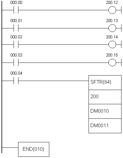
E.37 SHIFT REGISTER - Shifts the contents of a word for 1 bit to the left
| Description |
Instruction shifts the contents of word St for 1 bit to the left. The highest bit of the word St moves to the place of the lowest bit in the word St+1, the highest bit of the word St+1 moves to the position of the lowest bit in the word St+2 and so forth, up to the word E. The highest bit of the word E is irreversibly lost with every shifting. Input I defines whether “0” or “1” fills the lowest bit position. If the state of I line is ON, value is one, while OFF defines zero. Input P is used as clock for the instruction and switching it from OFF to ON changes the bit shift. State on R line can be OFF when the instruction can be executed and ON when all the bits within word range from St to E are set to “0”. As long as the state of R line isn’t set to OFF state, instruction cannot be executed. |
| Ladder symbol |
 |
| Limitations |
E has to be greater or equal to the address in parameter St. |
| Flag |
ER flag changes state to ON if St is lower address than E or if they are not in the same memory area. |
| Example |
 Upon fulfilling the condition on bit IR000.00, instruction uses one-second clock on bit 255.02 in order to move the contents of the word HR00. Bit IR200.00 will be ON every time the bit HR00.07 equals one. Upon fulfilling the condition on bit IR000.00, instruction uses one-second clock on bit 255.02 in order to move the contents of the word HR00. Bit IR200.00 will be ON every time the bit HR00.07 equals one. |
E.38 WORD SHIFT - Shifts whole words
| Description |
Instruction shifts the whole contents of the word St to an address greater by one than the current. Value of the word from the parameter St is moved to St+1 up to the the word defined with parameter E. Word that equals zero fills the place on the right for every shifting. Value of the word on the address from parameter E is irreversibly lost. |
| Ladder symbol |
 |
| Limitations |
E has to be greater or equal address to the one from parameter St. Words DM6144 - DM6655 cannot be used as operands St and E. |
| Flag |
ER flag changes state to ON if St is lower address than E or if they are not from the same memory area. |
E.39 ARITHMETIC SHIFT LEFT - Arithmetic shift left
| Description |
Instruction shifts the contents of the word Wd for one bit to the left. The lowest bit becomes “0”, while the highest bit is moved to carry bit. |
| Ladder symbol |
 |
| Limitations |
Words DM6144 - DM6655 se ne mogu koristiti za operand Wd. |
| Flag |
EQ flag changes state to ON if the contents of the word Wd equal zero. CY flag takes the value of the highest bit of theword Wd and changes state accordingly. |
E.40 ARITHMETIC SHIFT RIGHT - Arithmetic shift right
| Description |
Instruction shifts the contents of the word Wd for 1 bit to the right. The highest bit takes value “0”, while the lowest bit moves to carry bit (CY). |
| Ladder symbol |
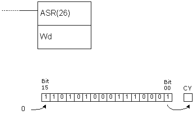 |
| Limitations |
Words DM 6144 - DM6655 cannot be used as operand Wd. |
| Flag |
EQ flag changes state to ON if the contents of the word Wd equal zero. CY flag takes the value of the lowest bit of the word Wd and changes state accordingly. |
E.41 ROTATE LEFT - Rotates the contents of a word for 1 bit to the left
| Description |
Instruction shifts the contents of the word Wd for one bit to left, using the carry bit CY. Bit from CY is then moved to the lowest bit to close the circle. |
| Ladder symbol |
 |
| Limitations |
Word DM6144 - DM6655 cannot be used as operand Wd. |
| Flag |
EQ flag changes state to ON if the contents of the word Wd equal zero. CY flag takes value of the highest bit of the word Wd and changes state accordingly. |
E.42 ROTATE RIGHT - Rotates the contents of a word for 1 bit to the right
| Description |
Instruction shifts the contents of the word Wd for one bit to the right, using the carry bit CY. Bit from CY is then moved to the highest bit to close the circle. |
| Ladder symbol |
 |
| Limitations |
Word DM6144 - DM6655 cannot be used as operand Wd. |
| Flag |
EQ flag changes state to ON if the contents of the word Wd equal zero. CY flag takes value of the lowest bit of the word Wd and changes state accordingly. |
E.43 ONE DIGIT SHIFT LEFT - Shifts word for one digit to the left
| Description |
Instruction shifts the contents of the word St for one digit to the left. The highest digit of the word E is irreversably lost and the lowest digit of the word St takes zero value. |
| Ladder symbol |
 |
| Limitations |
Words DM 6144 - DM6655 cannot be used as operands St and E. Operands St and E have to be in the same memory area, while the address of operand E has to be greater or equal to the address of operand St. |
| Flag |
ER flag changes state to ON if St and E are not from the same memory area or in case that the address of parameter E is lower than the address of parameter St. |
E.44 ONE DIGIT SHIFT RIGHT - Shifts word for one digit to the right
| Description |
Instruction shifts the contents of the word St for one digit to the right. The lowest digit of the word E is irreversably lost and the lowest digit of the word St takes zero value. |
| Ladder symbol |
 |
| Limitations |
Words DM 6144 - DM6655 cannot be used as operands St and E. Operands St and E have to be in the same memory area and the address of the operand E has to be lower or equal to the address of the operand St. |
| Flag |
ER flag changes state to ON if St and E are not from the same memory area or in case that the address of parameter E is higher than the address of parameter St. |
E.45 REVERSIBLE SHIFT REGISTER - Shifts words to the left or to the right
| Description |
Instruction is used for shifting one or several words in both directions, according to the states of the highest 4 bits in the control word C. The control word determines shifting direction, input value, clock and reset input. |
| Ladder symbol |
 |
| Limitations |
Words DM 6144 - DM6655 cannot be used as operands C, St and E. Operands St i E have to be from the same memory area and the address of the operand St has to be lower or equal to the address of the operand E. |
| Flag |
ER flag changes state to ON if St and E are not from the same memory area or the address of parameter St is higher than the address of parameter E. CY changes according to the state of the lowest bit of the word St or the highest bit of the word E, depending on the shifting direction set in the control word C. |
| Example |
 First instruction line determines the shifting direction, second determines input, third determines the clock and fourth determines reset. The shifting direction depends on the bit 12 of the control word. Depending on it, data bit moves to CY carry bit, while the opposite end becomes “0” or “1” depending on bit 13 of the control word. Condition for executing this instruction is located in the bit IR000.04, but besides this it is necessary to have the clock (bit 14 of the control word) ON. If the instruction is being executed with reset bit (bit 15 of the control word) OFF, all data bits as well as carry bit CY are set to “0”. First instruction line determines the shifting direction, second determines input, third determines the clock and fourth determines reset. The shifting direction depends on the bit 12 of the control word. Depending on it, data bit moves to CY carry bit, while the opposite end becomes “0” or “1” depending on bit 13 of the control word. Condition for executing this instruction is located in the bit IR000.04, but besides this it is necessary to have the clock (bit 14 of the control word) ON. If the instruction is being executed with reset bit (bit 15 of the control word) OFF, all data bits as well as carry bit CY are set to “0”. |
E.46 BCD INCREMENT - Increases the contents of a word by 1
| Description |
Instruction increases the contents of the word Wd by one when the condition is fulfilled. Incrementation does not affect the carry bit. |
| Ladder symbol |
 |
| Limitations |
Words DM 6144 - DM6655 cannot be used as operand Wd. |
| Flag |
ER flag changes state to ON if the contents of the word Wd are not BCD. EQ flag changes state to ON when the result of incrementation equals “0”. |
E.47 BCD DECREMENT - Decreases the contents of a word by 1
| Description |
Instruction decreases the contents of the word Wd by one when the condition is fulfilled. Decrementation does not affect the carry bit. |
| Ladder symbol |
 |
| Limitations |
Words DM6144 - DM6655 cannot be used as operand Wd. |
| Flag |
ER flag changes state to ON if the contents of the word Wd are not BCD. EQ flag changes state to ON when the result of decrementation equals “0”. |
E.48 BCD ADD - Adds two values
| Description |
Instruction adds the contents of words Au and Ad (Au + Ad + CY) and stores the result in location R. If the result is greater than 9999 carry bit CY is set. |
| Ladder symbol |
 |
| Limitations |
Words DM6144 - DM6655 cannot be used as operand R. |
| Flag |
ER flag changes state to ON if the contents of words Au and Ad are not BCD. EQ flag changes state to ON if the result equals “0”. CY flag changes state to ON if the result is greater than 9999. |
| Example |
Upon fulfilling the condition on bit IR000.02, carry bit is cleared and the value of memory location IR200 is added to the constant 6103. The result is stored in the memory location DM0100. The example further shows how to save the carry bit if the result was greater than 9999. If the result exceeded 9999, memory location DM0101 will take value “1” and if not it will take value “0”. In this way, locations DM0100 and DM0101 form one 32-bit word, which may prove to be useful.  |
E.49 SUBTRACT - Subtracts two values
| Description |
Instruction subtracts the contents of the word Su and a value of carry bit CY from the contents of the word Mi. The result is stored in the memory location R If the result is negative, carry bit CY is set and a 10’complement of the result is stored into R. To get the real result, just subtract the value in R from zero. |
| Ladder symbol |
 |
| Limitations |
Words DM 6144 - DM6655 cannot be used as operand R. |
| Flag |
ER flag changes state to ON if the contents of words Mi and Su are not BCD. EQ flag changes state to ON if the result equals “0”. CY flag changes state to ON if the result is negative. |
| Example |
 Carry bit status should be checked before the subtraction. It is best to clear it with CLC instruction. The check is more necessary after the subtraction, because there is chance of misinterpretation. If the carry bit is set (value is “1”) the result of subtraction is negative and the result word contains 10’ complement of the real result. When the condition is fulfilled on bit IR000.02, carry bit is cleared and the value of memory location DM0100 is subtracted from value of location IR201. The result is stored in the location HR10. Upon subtraction, carry bit CY is checked. If it is set, condition on SR255.04 (the very carry bit) will be fulfilled, clearing it anew and commencing the new subtraction in order to get the real result of the first subtraction. The second subtraction instruction subtracts the value of the result word HR10 from zero, storing the result into HR10 again. It is useful to set a certain bit for a programmer to have information on negative result. In the following example this bit is HR1100. Changing the state of carry bit to OFF doesn’t change the state of bit HR1100. Carry bit status should be checked before the subtraction. It is best to clear it with CLC instruction. The check is more necessary after the subtraction, because there is chance of misinterpretation. If the carry bit is set (value is “1”) the result of subtraction is negative and the result word contains 10’ complement of the real result. When the condition is fulfilled on bit IR000.02, carry bit is cleared and the value of memory location DM0100 is subtracted from value of location IR201. The result is stored in the location HR10. Upon subtraction, carry bit CY is checked. If it is set, condition on SR255.04 (the very carry bit) will be fulfilled, clearing it anew and commencing the new subtraction in order to get the real result of the first subtraction. The second subtraction instruction subtracts the value of the result word HR10 from zero, storing the result into HR10 again. It is useful to set a certain bit for a programmer to have information on negative result. In the following example this bit is HR1100. Changing the state of carry bit to OFF doesn’t change the state of bit HR1100.  Character “@” ahead of SUB(31) represents the differencial form of the instruction, or simply put, this instruction will not execute non-stop while the condition is fulfilled. Only changing the condition from OFF to ON executes the instruction. This means that the second subtraction instruction won’t take place immediately after the first one. Before executing the second instruction, it is necessary that bit IR000.02 changed state from OFF to ON at least once. Character “@” ahead of SUB(31) represents the differencial form of the instruction, or simply put, this instruction will not execute non-stop while the condition is fulfilled. Only changing the condition from OFF to ON executes the instruction. This means that the second subtraction instruction won’t take place immediately after the first one. Before executing the second instruction, it is necessary that bit IR000.02 changed state from OFF to ON at least once. |
E.50 BCD MULTIPLY - Multiplies two values
| Description |
Instruction multiplies values of locations Md and Mr and stores the result into memory locations R and R+1. |
| Ladder symbol |
 |
| Limitations |
Words DM6144 - DM6655 cannot be used as operand R. |
| Flag |
ER flag changes state to ON if the contents of words Mr and Md are not BCD. EQ flag changes state to ON if the result equals “0”. CY flag changes state to ON if the there is a carry in the result. |
| Example |
 Upon fulfilling the condition on bit IR000.00, instruction multiplies the values of memory locations IR013 and DM0005. The result is stored into two sequential memory locations HR07 and HR08. The result is stored so that HR08 contains higher bits and that HR07 contains lower bits. Upon fulfilling the condition on bit IR000.00, instruction multiplies the values of memory locations IR013 and DM0005. The result is stored into two sequential memory locations HR07 and HR08. The result is stored so that HR08 contains higher bits and that HR07 contains lower bits. |


