APPENDIX E Ladder diagram instructions (1/3)
INDIRECT ADDRESSING
Placing the character “*” ahead of operand from DM memory area allows us to use the indirect addressing. Simply put, value in the word *DM will be the address of the word that is the true operand. The picture below shows the MOV instruction with one operand given indirectly. The contents of location DM0003 equal “1433” which is actually a pointer marking the address DM1433 with contents “0005”. The result of this instruction will be moving the value “0005” from word DM1433 to word LR00.
In order to use the indirect addressing, contents of the word that is the indirect operand have to be in BCD format. Besides that, value of the contents of indirect operand must not be greater than the number of addresses in DM area.
 INSTRUCTION FORMAT
Operand is the address of a word or a bit in PLC controller memory (most of the instructions has one or more operands). The common term for a word is just “operand” and in the case of bit we call it “operand bit”. Also, operand can be a direct numerical value marked by character “#” placed ahead of the value (i.e.. #12, #345 etc).
The state of operand bit can be ON or OFF. ON means that its logic state equals “1”, while OFF stands for “0”. Besides these, terms “set” and “reset” are also used.
Symbols SV and PV commonly appear in instruction syntax. These abbreviations stand for “
Set Value” and “
Present Value” and are most frequently encountered with instructions concerning counters and timers.
DIFFERENTIAL INSTRUCTION FORM
Differential form is supported by almost all of the instructions. What differs this form from the classical one is the character “@” placed ahead of the name of the instruction. This form ensures that the instruction with condition fulfilled will not be executed in every cycle, but only when its condition changes state from OFF to ON. Differential from is commonly used because it has a lot of applications in real-life problems.
 DIFFERENCE BETWEEN BINARY AND BCD REPRESENTATIONS OF WORD CONTENTS
Generally, there are two dominant ways for comprehending values of memory locations. The first is binary and is related to the contents of the word which is treated as a union of 16 bits. Value is calculated as a sum of each bit (0 or 1) multiplied by 2 on power
n, where
n represents the position of bit in the word. Bit of the least value has position zero, while bit of greatest value has position 15.
BCD is an abbreviation for “Binary Coded Decimal number”. It is nothing more than representing each decimal figure with 4 bits, similar to binary coding hence the name comes from. The picture below shows the difference between binary and BCD representations of the number. Same contents can be interpreted as either 612 or 264. For that reason, proper attention should be given to the format of the value within the word that will be sent to the instruction as an operand.
 LADDER DIAGRAM INSTRUCTIONS
Instructions may be divided into several basic groups according to their purpose :
- Input instructions
- Output instructions
- Control instructions
- Timer/counter instructions
- Data comparison instructions
- Data movement instructions
- Increment/decrement instructions
- BCD/binary calculation instructions
- Data conversion instructions
- Logic instructions
- Special calculation instructions
- Subroutine instructions
- Interrupt control instructions
- I/O units instructions
- Display instructions
- High-speed counter control instructions
- Damage diagnosis instructions
- Special system instructions
Each of these instruction groups is introduced with a brief description in the following tables and with more detailed examples and descriptions afterwards.
Sequence Input Instructions
| Instruction |
Mnemonic |
Code
|
Function |
| LOAD |
LD |
0 |
Connects an NO condition to the left bus bar. |
| LOAD NOT |
LD NOT |
0 |
Connects an NC condition to the left bus bar. |
| AND |
AND |
0 |
Connects an NO condition in series with the previous condition |
| AND NOT |
AND NOT |
0 |
Connects an NC condition in series with the previous condition |
| OR |
OR |
0 |
Connects an NO condition in parallel with the previous condition. |
| OR NOT |
OR NOT |
0 |
Connects an NC condition in parallel with the previous condition. |
| AND LOAD |
AND LD |
0 |
Connects two instruction blocks in series. |
| OR LOAD |
OR LD |
0 |
Connects two instruction blocks in parallel. |
Sequence Output Instructions
| Instruction |
Mnemonic |
Code
|
Function |
| OUTPUT |
OUT |
0 |
Outputs the result of logic to a bit. |
| OUT NOT |
OUT NOT |
0 |
Reverses and outputs the result of logic to a bit. |
| SET |
SET |
0 |
Force sets (ON) a bit. |
| RESET |
RESET |
0 |
Force resets (OFF) a bit. |
| KEEP |
KEEP |
11 |
Maintains the status of the designated bit. |
| DIFFERENTIATE UP |
DIFU |
13 |
Turns ON a bit for one cycle when the execution condition goes from OFF to ON. |
| DIFFERENTIATEDOWN |
DIFD |
14 |
Turns ON a bit for one cycle when the execution condition goes from ON to OFF. |
Sequence Control Instructions
| Instruction |
Mnemonic |
Code |
Function |
| NO OPERATION |
NOP |
00 |
--- |
| END |
END |
01 |
Required at the end of the program. |
| INTERLOCK |
IL |
02 |
It the execution condition for IL(02) is OFF, all outputs are turned OFF and all timer PVs reset between IL(02) and the next ILC(03). |
| INTERLOCKCLEAR |
ILC |
03 |
ILC(03) indicates the end of an interlock (beginning at IL(02)). |
| JUMP |
JMP |
04 |
If the execution condition for JMP(04) is ON, all instructions between JMP(04) and JME(05) are treated as NOP(OO). |
| JUMP END |
JME |
05 |
JME(05) indicates the end of a jump (beginning at JMP(04)). |
Timer/Counter Instructions
| Instruction |
Mnemonic |
Code
|
Function |
| TIMER |
TIM |
0 |
An ON-delay (decrementing) timer. |
| COUNTER |
CNT |
0 |
A decrementing counter. |
| REVERSIBLECOUNTER |
CNTR |
12 |
Increases or decreases PV by one. |
| HIGH-SPEEDTIMER |
TIMH |
15 |
A high-speed, ON-delay (decrementing) timer. |
Data Comparison Instructions
| Instruction |
Mnemonic |
Code
|
Function |
| COMPARE |
CMP |
20 |
Compares two four-digit hexadecimal values. |
| DOUBLECOMPARE |
CMPL |
60 |
Compares two eight-digit hexadecimal values. |
| BLOCK COMPARE |
(@)BCMP |
68 |
Judges whether the value of a word is within 16 ranges (defined by lower and upper limits). |
| TABLE COMPARE |
(@)TCMP |
85 |
Compares the value of a word to 16 consecutive words. |
Data Movement Instructions
| Instruction |
Mnemonic |
Code
|
Function |
| MOVE |
(@)MOV |
21 |
Copies a constant or the content of a word to a word. |
| MOVE NOT |
(@)MVN |
22 |
Copies the complement of a constant or the content of a word to a word. |
| BLOCKTRANSFER |
(@)XFER |
70 |
Copies the content of a block of up to 1,000 consecutive words to a block of consecutive words. |
| BLOCK SET |
(@)BSET |
71 |
Copies the content of a word to a block of consecutive words. |
| DATA EXCHAGE |
(@)XCHG |
73 |
Exchanges the content of two words. |
| SINGLE WORDDISTRIBUTE |
(@)DIST |
80 |
Copies the content of a word to a word (whose address is determined by adding an offset to a word address). |
| DATA COLLECT |
(@)COLL |
81 |
Copies the content of a word (whose address is determined by adding an offset to a word address) to a word. |
| MOVE BIT |
(@)MOVB |
82 |
Copies the specified bit from one word to the specified bit of a word. |
| MOVE DIGIT |
(@)MOVD |
83 |
Copies the specified digits (4-bit units) from a word to the specified digits of a word. |
Shift Instructions
| Instruction |
Mnemonic |
Code
|
Function |
| SHIFT REGISTER |
SFT |
0/10 |
Copies the specified bit (0 or 1) into the rightmost bit of a shift register and shifts the other bits one bit to the left. |
| WORD SHIFT |
(@)WSFT |
16 |
Creates a multiple-word shift register that shifts data to the left in one-word units. |
| ASYNCHRONOUSSHIFT REGISTER |
(@)ASFT |
17 |
Creates a shift register that exchanges the contents of adjacent words when one is zero and the other is not. |
| ARITHMETICSHIFT LEFT |
(@)ASL |
25 |
Shifts a 0 into bit 00 of the specified word and shifts the other bits one bit to the left. |
| ARITHMETICSHIFT RIGHT |
(@)ASR |
26 |
Shifts a 0 into bit 15 of the specified word and shifts the other bits one bit to the right. |
| ROTATE LEFT |
(@)ROL |
27 |
Moves the content of CY into bit 00 of the specified word, shifts the other bits one bit to the left, and moves bit 15 to CY. |
| ROTATE RIGHT |
(@)ROR |
28 |
Moves the content of CY into bit 15 of the specified word, shifts the other bits one bit to the left, and moves bit 00 to CY. |
| ONE DIGITSHIFT LEFT |
(@)SLD |
74 |
Shifts a 0 into the rightmost digit (4-bit unit) of the shift register and shifts the other digits one digit to the left. |
| ONE DIGITSHIFT RIGHT |
(@)SRD |
75 |
Shifts a 0 into the rightmost digit (4-bit unit) of the shift register and shifts the other digits one digit to the right. |
| REVERSIBLESHIFT REGISTER |
(@)SFTR |
84 |
Creates a single or multiple-word shift register that can shift data to the left or right. |
Increment/Decrement Instructions
| Instruction |
Mnemonic |
Code
|
Function |
| INCREMENT |
(@)INC |
38 |
Increments the BCD content of the specified word by 1. |
| DECREMENT |
(@)DEC |
39 |
Decrements the BCD content of the specified word by 1. |
BCD/Binary Calculation Instructions
| Instruction |
Mnemonic |
Code
|
Function |
| BCD ADD |
(@)ADD |
30 |
Adds the content of a word (or a constant). |
| BCD SUBTRACT |
(@)SUB |
31 |
Subtracts the contents of a word (or constant) and CY from the content of a word (or constant). |
| BDC MULTIPLY |
(@)MUL |
32 |
Multiplies the content of two words (or contents). |
| BCD DIVIDE |
(@)DIV |
33 |
Divides the contents of a word (or constant) by the content of a word (or constant). |
| BINARY ADD |
(@)ADB |
50 |
Adds the contents of two words (or constants) and CY. |
| BINARY SUBTRACT |
(@)SBB |
51 |
Subtracts the content of a word (or constant) an CY from the content of the word (or constant). |
| BINARY MULTIPLY |
(©)MLB |
52 |
Multiplies the contents of two words (or constants). |
| BINARY DIVIDE |
(@)DVB |
53 |
Divides the content of a word (or constant) by the content of a word and obtains the result and remainder. |
| DOUBLE BCD ADD |
(@)ADDL |
54 |
Add the 8-digit BCD contents of two pairs of words (or constants) and CY. |
| DOUBLE BCDSUBTRACT |
(@)SUBL |
55 |
Subtracts the 8-digit BCD contents of a pair of words (or constants) and CY from the 80digit BCD contents of apair of words (or constants) |
| DOUBLE BCDMULITPLY |
(@)MULL |
56 |
Multiplies the 8-digit BCD contents of two pairs of words (or constants). |
| DOUBLE BCD DIVIDE |
(@)DIVL |
57 |
Divides the 8-digit BCD contents of a pair of words (or constants) by the 8–digits BCD contents of a pair of words (or constants) |
Data Conversion Instructions
| Instruction |
Mnemonic |
Code
|
Function |
| BCD TO BINARY |
(@)BIN |
23 |
Converts 4-digit BCD data to 4-digit binary data. |
| BINARY TO BCD |
(@)BCD |
24 |
Converts 4-digit binary data to 4 digit BCD data. |
| 4 to 16 DECODER |
(@)MLPX |
76 |
Takes the hexadecimal value of the specified digit(s) in a word and turn ON the corresponding bit in a word(s). |
| 16 to 4 DECODER |
(@)DPMX |
77 |
Identifies the highest ON bit in the specified word(s) and moves the hexadecimal value(s) corresponding to its location to the specified digit(s) in a word. |
| ASCII CODE CONVERT |
(@)ASC |
86 |
Converts the designated digit(s) of a word into the equivalent 8-bit ASCII code. |
Logic Instructions
| Instruction |
Mnemonic |
Code
|
Function |
| COMPLEMENT |
(@)COM |
29 |
Turns OFF all ON bits and turns ON all OFF bits in the specified word |
| LOGICAL AND |
(@)ANDW |
34 |
Logically ANDs the corresponding bits of two word (or constants) |
| LOGICAL OR |
(@)ORW |
35 |
Logically ORs the corresponding bits of two word (or constants) |
| EXCLUSIVE OR |
(@)XORW |
36 |
Exclusively ORs the corresponding bits of two words (or constants) |
| EXCLUSIVE NOR |
(@)XNRW |
37 |
Exclusively NORs the corresponding bits of two words (or constants). |
Special Calculation Instructions
| Instruction |
Mnemonic |
Code
|
Function |
| BIT COUNTER |
(@)BCNT |
67 |
Counts the total number of bits that are ON in the specified block |
Subroutine Instructions
| Instruction |
Mnemonic |
Code
|
Function |
| SUBROUTINE ENTER |
(@)SBS |
91 |
Executes a subroutine in the main program. |
| SUBROUTINE ENTRY |
SBN |
92 |
Marks the beginning of a subroutine program. |
| SUBROUTINE RETURN |
RET |
93 |
Marks the end of a subroutine program. |
| MACRO |
MACRO |
99 |
Calls and executes the specified subroutine, substituting the specified input and output words for the input and output words in the subroutine. |
Interrupt Control Instructions
| Instruction |
Mnemonic |
Code
|
Function |
| INTERVAL TIMER |
(@)STIM |
69 |
Controls interval timers used to perform scheduled interrupts. |
| INTERRUPT CONTROL |
(@)INT |
89 |
Performs interrupts control, such as masking and unmasking the interrupt bits for I/O interrupts. |
Step Instructions
| Instruction |
Mnemonic |
Code
|
Function |
| STEP DEFINE |
STEP |
08 |
Defines the start of a new step and resets the previous step when used with a control bit. Defines the end of step execution when used without a control bit. |
| STEP START |
SNXT |
09 |
Starts the execution of the step when used with a control bit. |
Peripheral Device Control Instructions
| Instruction |
Mnemonic |
Code
|
Function |
| BCD TO BINARY |
(@)BIN |
23 |
Converts 4-digit BCD data to 4-digit binary data. |
| BINARY TO BCD |
(@)BCD |
24 |
Converts 4-digit binary data to 4-digit BCD data. |
| 4 to 16 DECODER |
(@)MLPX |
76 |
Takes the hexadecimal value of the specified digit(s) in a word and turn ON the corresponding bit in a word(s). |
| 16 to 4 DECODER |
(@)DPMX |
77 |
Identifies the highest ON bit in the specified word(s) and moves the hexadecimal value(s) corresponding to its location to the specified digit(s) in a word. |
| ASCII CODE CONVERT |
(@)ASC |
86 |
Converts the designated digit(s) of a word into the equivalent 8-bit ASCII code. |
I/O Units Instructions
| Instruction |
Mnemonic |
Code
|
Function |
| 7-SEGMENT DECODER |
(@)SDEC |
78 |
Converts the designated digit(s)of a word into an 8-bit, 7-segment display code. |
| I/O REFRESH |
(@)IORF |
97 |
Refreshes the specified I/O word. |
Display Instructions
| Instruction |
Mnemonic |
Code
|
Function |
| MEASSAGE |
(@)MSG |
46 |
Reads up to 8 words of ASCII code (16 characters) from memory and displays the message on the Programming Console or other Peripheral Device. |
High Speed Counter Control Instructions
| Instruction |
Mnemonic |
Code
|
Function |
| MODE CONTROL |
(@)INI |
61 |
Starts and stops counter operation, compares and changes counter PVs, and stops pulse output. |
| PV READ |
(@)PRV |
62 |
Reads counter PVs and status data. |
| COMPARE TABLE LOAD |
(@)CTBL |
63 |
Compares counter PVs and generates a direct table or starts operation. |
Damage Diagnosis Instructions
| Instruction |
Mnemonic |
Code
|
Function |
| FAILURE ALARM |
(@)FAL |
06 |
Generates a non-fatal error when executed. The Error/Alarm indicator flashes and the CPU continues operating. |
| SEVERE FAILURE ALARM |
FAL |
07 |
Generates a fatal error when executed. The Error/Alarm indicator lights and the CPU stops operating. |
Special System Instructions
| Instruction |
Mnemonic |
Code
|
Function |
| SET CARRY |
(@)STC |
40 |
Sets Carry Flag 25504 to 1. |
| CLEAR CARRY |
(@)CLC |
41 |
Sets Carry Flag 25504 to 0. |
E.1 LOAD - Normally open output
| Description |
First condition, that any logical block in the ladder diagram starts with, corresponds to LOAD or LOAD NOT instructions. Both of these instructions require one line in mnemonic code. On the right of these instructions any executive instruction may be used. |
| Ladder symbol |
 |
| Limitations |
There are no limitations, except that it is used as the first instruction from left to right. |
| Flag |
It has no effect on any particular flag. |
| Example |
 Pressing the button on the input “00” in the word IR000 activates the relay “00” on the output of PLC controller. Conditional instruction doesn’t have be from input memory area; it can be any bit from other memory areas, i.e. SR area as in the following example.
 When one of the instructions activates the bit “00” in the word SR200, bit “00” is activated in the output word IR010. In a word, every ON state of the bit at input causes the ON state at output.
 |
E.2 LOAD NOT - Normally closed input
| Description |
First condition, that any logical block in the ladder diagram starts with, corresponds to LOAD or LOAD NOT instructions. Both of these instructions require one line in mnemonic code. On the right of these instructions any executive instruction may be used. |
| Ladder symbol |
 |
| Limitations |
There are no limitations, except that it is used as the first instruction from left to right. |
| Flag |
It has no effect on any particular flag. |
| Example |
 Pressing the button on the input “00” in the word IR000 activates the relay “00” on the output of PLC controller. Conditional instruction doesn’t have be from input memory area; it can be any bit from other memory areas, i.e. SR area as in the following example.
 When one of the instructions activates the bit “00” in the word SR200, bit “00” is activated in the output word IR010. In a word, every ON state of the bit at input causes the OFF state at output.
 |
E.3 AND - Logical "AND" with normally open contacts
| Description |
When two are linked serially in one instruction line, first of them corresponds to instructions LOAD or LOAD NOT, while the other represents instructions AND or AND NOT. |
| Ladder symbol |
 |
| Limitations |
There are no limitations. |
| Flag |
It has no effect on any particular flag. |
| Example |
 After the LOAD instruction on ‘00’ input, AND instruction is linked to input ‘01’. Instruction on the right will be executed only when both of the conditions from the line are fulfilled, i.e. when both inputs ‘00’ and ‘01’ are in the ON state.
 |
E.4 AND NOT - Logical "AND" with normally closed contacts
| Description |
When two or more conditions are linked serially in one instruction line, first of them corresponds to instruction LOAD or LOAD NOT, while the other represents instruction AND or AND NOT. |
| Ladder symbol |
 |
| Limitations |
There are no limitations. |
| Flag |
It has no effect on any particular flag. |
| Example |
 After the LOAD instruction on ‘00’ input, AND NOT instruction is linked to input ‘01’. Instruction on the right will be executed only when both of the conditions from the line are fulfilled, i.e. when input ‘00’ is in ON state and input ‘01’ is in OFF state.
 |
E.5 OR - Logical "OR" with normally open contacts
| Description |
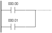
When two or more conditions coexist on separate, paralel lines that connect at a given point, the first condition corresponds to LOAD or LOAD NOT instructions, while others correspond to OR or OR NOT instructions. |
| Ladder symbol |
 |
| Limitations |
There are no limitations. |
| Flag |
It has no effect on any particular flag. |
| Example |
 Inputs ‘00’ and ‘01’ are in OR relation with the output ‘00’. One of the inputs with ON state is sufficient to activate the output ‘00’.
 |
E.6 OR NOT - Logical "OR" with normally closed contacts
| Description |
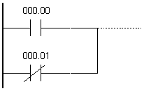
When two or more conditions coexist on separate, paralel lines that connect at a given point, the first condition corresponds to LOAD or LOAD NOT instructions, while others correspond to OR or OR NOT instructions. |
| Ladder symbol |
 |
| Limitations |
There are no limitations. |
| Flag |
It has no effect on any particular flag. |
| Example |
 Inputs ‘000.00’ and ‘000.01’ are in OR NOT relation with the output ‘010.00’. Bit ‘010.00’ will retain ON state until bit “01” changes to ON state (thus breaking the connection, because it is normally closed). One of the inputs with ON state is sufficient to activate the output ‘00’.
 |
E.7 OUTPUT - Normally open output
| Description |
The easiest way for getting results that fulfill input conditions is their direct connection to the instructions OUTPUT and OUTPUT NOT. These instructions are used for controlling the status bit, which is defined as the instruction carrier. When OUTPUT instruction is used, bit assigned to it will be ON if the execution condition is ON, and it will be OFF if the execution condition is OFF. |
| Ladder symbol |
 |
| Limitations |
Attention should be paid not to “overlap” the instructions concerning the bit being controlled. |
| Flag |
It has no effect on any particular flag. |
| Example |
 Bit IR010.00 will remain ON as long as bit IR000.00 is ON. When bit IR000.00 changes to OFF, bit IR010.00 also changes to OFF.
This instruction cannot be used for assigning ON or OFF states to more than one bit. In case that there is a need for assigning values to all of the bits in word, it can be done only one bit at a time.
 |
E.8 OUTPUT NOT - Normally closed output
| Description |
The easiest way for getting results that fulfill input conditions is their direct connection to the instructions OUTPUT and OUTPUT NOT. These instructions are used for controlling the status bit, which is defined as the instruction carrier. When OUTPUT instruction is used, bit assigned to it will be ON if the execution condition is OFF, and it will be OFF if the execution condition is ON. |
| Ladder symbol |
 |
| Limitations |
Attention should be paid not to “overlap” the instructions concerning the bit being controlled. |
| Flag |
It has no effect on any particular flag. |
| Example |
 Bit IR010.00 will remain ON as long as bit IR000.00 is OFF, while prelaskom changing bit IR000.00 to ON changes bit IR010.00 to OFF.
This instruction cannot be used for assigning ON or OFF states to more than one bit. In case that there is a need for assigning values to all of the bits in word, it can be done only one bit at a time.
 |
E.9 SET - Changes bit state to ON
| Description |
Instruction changes the state of the specified bit to ON when the execution condition is ON. In case that the condition is OFF, bit state remains unchanged (unlike the instruction OUT which changes bit state to OFF even when the condition is OFF). |
| Ladder symbol |
 |
| Limitations |
There are no limitations. |
| Flag |
It has no effect on any particular flag. |
| Example |
 If condition state on bit IR000.00 changes to ON, state of bit IR200.00 also changes to ON. When condition state of bit IR000.00 changes from ON to OFF, bit IR200.00 remains ON.
 |
E.10 RESET - Changes bit state to OFF
| Description |
Instruction changes the state of the specified bit to OFF when the execution condition is ON. In case that the condition is OFF, bit state remains unchanged. |
| Ladder symbol |
 |
| Limitations |
There are no limitations. |
| Flag |
It has no effect on any particular flag. |
| Example |
 If condition state on bit IR000.00 changes to ON, state of bit IR200.00 changes to OFF. When condition state of bit IR000.00 changes from ON to OFF, bit IR200.00 remains OFF.
 |
E.11 KEEP - Changes bit state according to 2 inputs
| Description |
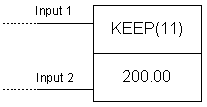
Instruction is used for maintaining the status of corresponding bit according to 2 inputs. The first input changes bit state to ON whenever the condition of the first line is fulfilled, while the second changes bit state to OFF whenever the condition of the second line is fulfilled. Bit state remains unchanged as long as inputs remain unchanged. |
| Ladder symbol |
 |
| Flag |
It has no effect on any particular flag. |
| Example |
 When the state of bit IR000.00 changes to ON bit IR200.00 also changes to ON. If bit IR000.01 changes to ON, bit IR200.00 changes to OFF and remains OFF until state of bit IR000.00 is ON again.
 |
E.12 DIFFERENTIATE UP - Changes bit state to ON for duration of one cycle
| Description |
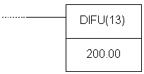
Instruction changes bit state to ON during one cycle when the preceding condition is fulfilled. |
| Ladder symbol |
 |
| Flag |
It has no effect on any particular flag. |
| Example |
 Instruction changes state of bit IR200.00 to ON for duration of one cycle. If bit IR000.00 is ON, bit IR200.00 changes to ON for duration of one scan cycle.
 |
E.13 DIFFERENTIATE DOWN - Changes bit state to OFF for duration of one cycle
| Description |
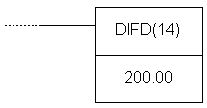
Instruction changes bit state to OFF during one cycle when the preceding condition is fulfilled. |
| Ladder symbol |
 |
| Flag |
It has no effect on any particular flag. |
| Example |
 If bit IR000.00 is ON, state of bit IR200.00 changes to OFF for duration of one scan cycle.
 |
E.14 NO OPERATION - No operation
| Description |
Generally, usage of this instruction in programs is not recommended. When PLC gets to this instruction nothing happens and the following instruction is executed. |
| Ladder symbol |
 |
| Flag |
It has no effect on any particular flag. |
E.15 INTERLOCK - Interlock
| Description |
Instruction IL is always used in pair with the instruction ILC. Their purpose is to reset all the outputs, flags, control bits, timers and counters that are within instructions between IL and ILC. Timers and counters stop working and retain values they had at the moment of executing IL instruction. It is possible to have multiple IL instructions and to reset one or more parts of the program, accordingly. Instruction is executed when condition state changes from ON to OFF! |
| Ladder symbol |
 |
| Flag |
It has no effect on any particular flag. |
E.16 INTERLOCK CLEAR - End of the program part encompassed by interlock
| Description |
Instruction ILC is always used in pair with instruction IL. When the condition of instruction IL is fulfilled all the outputs, flags, control bits, timers and counters that are within instructions between IL and ILC are reset. Timers and counters stop working and retain values they had at the moment of executing IL instruction. |
| Ladder symbol |
 |
| Flag |
It has no effect on any particular flag. |
E.17 END - End of program
| Description |
This is mandatory instruction at the end of every program. Any instruction following this one will not be executed. It can be used for debugging purposes in program, so as to designate the point where the monitoring of program execution stops. If the program uses subroutines, it is necesssary to have instruction END following the last subroutine. |
| Ladder symbol |
 |
| Limitations |
There are no limitations. |
| Flag |
Changes states of flags ER, CY, GR, EQ and LE to OFF. |
E.18 JUMP - Jump to another location in the program
| Description |
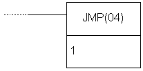
Certain part of the program may be skipped depending on the state of defined condition for jump execution. Jumps can be created using JUMP (JMP(04)) or JUMP END (JME(05)) instructions. If condition state is ON, program executes normally, as if the instruction was never used. If status of execution condition is OFF, program execution continues from the JUMP END instruction corresponding to JUMP instruction. Which JUMP END corresponds to which JUMP instruction is defined with a number that follows the instruction. Value 0 can be used unlimited number of times in the course of program for this purpose, while each of other 99 available numbers may be used only once. |
| Ladder symbol |
 |
| Limitations |
Total number of JUMP and JUMP END pairs cannot exceed 99. Each value from 1-99 range can be used only once. |
| Flag |
It has no effect on any particular flag. |
E.19 JUMP END - Location where the program execution continues after JUMP
| Description |
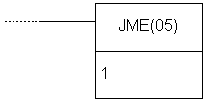
Instruction JME is used in pair with JMP instruction as integral part of it. If there is no JME assigned to JMP instruction, program will report an error. |
| Ladder symbol |
 |
| Limitations |
Total number of JUMP and JUMP END pairs cannot exceed 99. Each value from 1-99 range can be used only once. |
| Flag |
It has no effect on any particular flag. |
| Example |
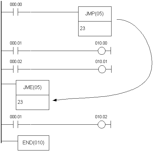 When the state of bit IR000.00 changes to OFF, jump instruction skips all the instruction lines between itself and the corresponding JME instruction.
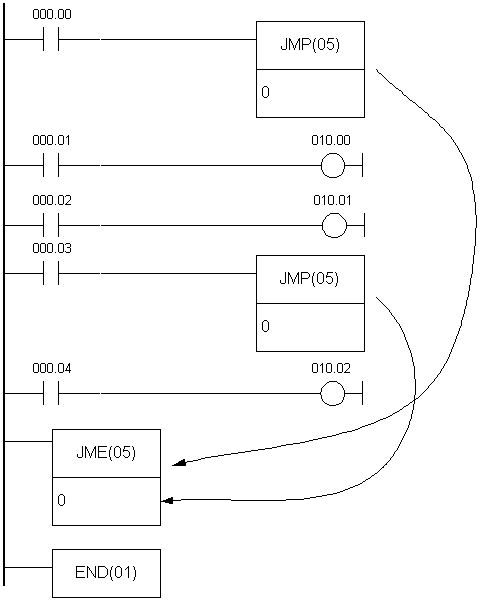
Another way for using jump instruction is assigning value “0” to JMP instruction. Unlimited number of jumps can be programmed in this way and the destination for each of these is a unique location defined with instruction JUMP END with index 0. Instruction JUMP END with parameter 0 may be used multiple times in the program. In that case, program execution after the jump defined with JUMP (index 0) continues from the first following JUMP END instruction with this index. Time of execution with this form of jump function is somewhat longer, as the program must first locate the closest appropriate JUMP END instruction. The following example demonstrates programming greater number of jump functions ending at the same destination:
Changing the state of bits IR000.00 or IR000.03 to OFF executes the jump to the line containing instruction JME.
 |
E.20 TIMER - Timer with 0.1s resolution
| Description |
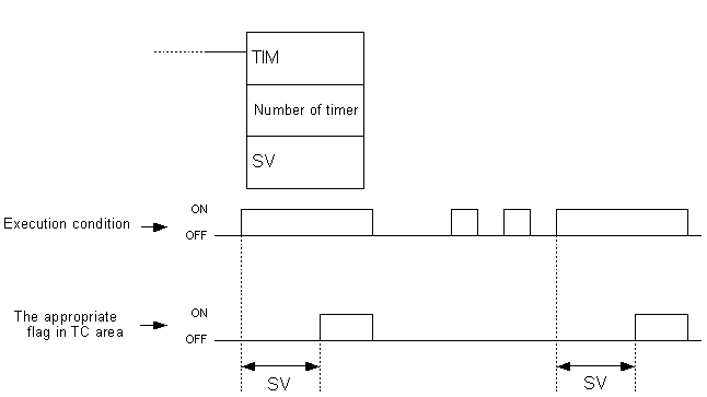
Timers are complex instructions with the purpose of separating two programming actions. Changing the state of condition to ON starts the timing with 0.1s increments starting from zero.
Value of parameter SV (abbreviation for Set Value) is multiplied by 0.1 s, the result being total time in seconds. Value given in the middle part of the block is called TC number. Each TC number can be used for defining one couner or timer. It can take values from 000 - 127 range. Lower part of the block is reserved for displaying the starting value of timer. Word with this role can belong to sectors IR, AR, DM, HR, LR or can be given as a constant, with values from 000.0 - 999.9 range. The most common and the simplest way to apply a timer is to have a constant here, whether given directly or programmed on some memory location (if parameter SV is given as a constant, it is necessary to put character “#” ahead of value). |
| Ladder symbol |
 |
| Limitations |
The number of timer cannot be used for counter or another timer. |
| Flag |
Affects the appropriate flag in TC area. |
| Example |
 Changing the state of bit IR000.00 to ON starts the timing (in this case, time is 100*0.1s=10 seconds). After the passing of given period of time, the appropriate bit IM002 changes state to ON, thus fulfilling the condition for executing the instructions on the right (in this case bit IR010.01 changes state to ON).
Condition bit must be constantly ON for a given time period for bit TIM002 to be set. If condition state changes to OFF during the given time period, timer resets and goes back to the beginning of period.
 |


 INSTRUCTION FORMAT
Operand is the address of a word or a bit in PLC controller memory (most of the instructions has one or more operands). The common term for a word is just “operand” and in the case of bit we call it “operand bit”. Also, operand can be a direct numerical value marked by character “#” placed ahead of the value (i.e.. #12, #345 etc).
The state of operand bit can be ON or OFF. ON means that its logic state equals “1”, while OFF stands for “0”. Besides these, terms “set” and “reset” are also used.
Symbols SV and PV commonly appear in instruction syntax. These abbreviations stand for “Set Value” and “Present Value” and are most frequently encountered with instructions concerning counters and timers.
DIFFERENTIAL INSTRUCTION FORM
Differential form is supported by almost all of the instructions. What differs this form from the classical one is the character “@” placed ahead of the name of the instruction. This form ensures that the instruction with condition fulfilled will not be executed in every cycle, but only when its condition changes state from OFF to ON. Differential from is commonly used because it has a lot of applications in real-life problems.
 DIFFERENCE BETWEEN BINARY AND BCD REPRESENTATIONS OF WORD CONTENTS
Generally, there are two dominant ways for comprehending values of memory locations. The first is binary and is related to the contents of the word which is treated as a union of 16 bits. Value is calculated as a sum of each bit (0 or 1) multiplied by 2 on power n, where n represents the position of bit in the word. Bit of the least value has position zero, while bit of greatest value has position 15.
BCD is an abbreviation for “Binary Coded Decimal number”. It is nothing more than representing each decimal figure with 4 bits, similar to binary coding hence the name comes from. The picture below shows the difference between binary and BCD representations of the number. Same contents can be interpreted as either 612 or 264. For that reason, proper attention should be given to the format of the value within the word that will be sent to the instruction as an operand.
 LADDER DIAGRAM INSTRUCTIONS
Instructions may be divided into several basic groups according to their purpose :
- Input instructions
- Output instructions
- Control instructions
- Timer/counter instructions
- Data comparison instructions
- Data movement instructions
- Increment/decrement instructions
- BCD/binary calculation instructions
- Data conversion instructions
- Logic instructions
- Special calculation instructions
- Subroutine instructions
- Interrupt control instructions
- I/O units instructions
- Display instructions
- High-speed counter control instructions
- Damage diagnosis instructions
- Special system instructions
Each of these instruction groups is introduced with a brief description in the following tables and with more detailed examples and descriptions afterwards.
Sequence Input Instructions

 Pressing the button on the input “00” in the word IR000 activates the relay “00” on the output of PLC controller. Conditional instruction doesn’t have be from input memory area; it can be any bit from other memory areas, i.e. SR area as in the following example.
 When one of the instructions activates the bit “00” in the word SR200, bit “00” is activated in the output word IR010. In a word, every ON state of the bit at input causes the ON state at output.
 Pressing the button on the input “00” in the word IR000 activates the relay “00” on the output of PLC controller. Conditional instruction doesn’t have be from input memory area; it can be any bit from other memory areas, i.e. SR area as in the following example.
 When one of the instructions activates the bit “00” in the word SR200, bit “00” is activated in the output word IR010. In a word, every ON state of the bit at input causes the OFF state at output.
 After the LOAD instruction on ‘00’ input, AND instruction is linked to input ‘01’. Instruction on the right will be executed only when both of the conditions from the line are fulfilled, i.e. when both inputs ‘00’ and ‘01’ are in the ON state.
 After the LOAD instruction on ‘00’ input, AND NOT instruction is linked to input ‘01’. Instruction on the right will be executed only when both of the conditions from the line are fulfilled, i.e. when input ‘00’ is in ON state and input ‘01’ is in OFF state.
 Inputs ‘00’ and ‘01’ are in OR relation with the output ‘00’. One of the inputs with ON state is sufficient to activate the output ‘00’.
 Inputs ‘000.00’ and ‘000.01’ are in OR NOT relation with the output ‘010.00’. Bit ‘010.00’ will retain ON state until bit “01” changes to ON state (thus breaking the connection, because it is normally closed). One of the inputs with ON state is sufficient to activate the output ‘00’.
 Bit IR010.00 will remain ON as long as bit IR000.00 is ON. When bit IR000.00 changes to OFF, bit IR010.00 also changes to OFF.
This instruction cannot be used for assigning ON or OFF states to more than one bit. In case that there is a need for assigning values to all of the bits in word, it can be done only one bit at a time.
 Bit IR010.00 will remain ON as long as bit IR000.00 is OFF, while prelaskom changing bit IR000.00 to ON changes bit IR010.00 to OFF.
This instruction cannot be used for assigning ON or OFF states to more than one bit. In case that there is a need for assigning values to all of the bits in word, it can be done only one bit at a time.
 If condition state on bit IR000.00 changes to ON, state of bit IR200.00 also changes to ON. When condition state of bit IR000.00 changes from ON to OFF, bit IR200.00 remains ON.
 If condition state on bit IR000.00 changes to ON, state of bit IR200.00 changes to OFF. When condition state of bit IR000.00 changes from ON to OFF, bit IR200.00 remains OFF.
 When the state of bit IR000.00 changes to ON bit IR200.00 also changes to ON. If bit IR000.01 changes to ON, bit IR200.00 changes to OFF and remains OFF until state of bit IR000.00 is ON again.
 Instruction changes state of bit IR200.00 to ON for duration of one cycle. If bit IR000.00 is ON, bit IR200.00 changes to ON for duration of one scan cycle.
 If bit IR000.00 is ON, state of bit IR200.00 changes to OFF for duration of one scan cycle.


 When the state of bit IR000.00 changes to OFF, jump instruction skips all the instruction lines between itself and the corresponding JME instruction.
Another way for using jump instruction is assigning value “0” to JMP instruction. Unlimited number of jumps can be programmed in this way and the destination for each of these is a unique location defined with instruction JUMP END with index 0. Instruction JUMP END with parameter 0 may be used multiple times in the program. In that case, program execution after the jump defined with JUMP (index 0) continues from the first following JUMP END instruction with this index. Time of execution with this form of jump function is somewhat longer, as the program must first locate the closest appropriate JUMP END instruction. The following example demonstrates programming greater number of jump functions ending at the same destination:
Changing the state of bits IR000.00 or IR000.03 to OFF executes the jump to the line containing instruction JME.


 Changing the state of bit IR000.00 to ON starts the timing (in this case, time is 100*0.1s=10 seconds). After the passing of given period of time, the appropriate bit IM002 changes state to ON, thus fulfilling the condition for executing the instructions on the right (in this case bit IR010.01 changes state to ON).
Condition bit must be constantly ON for a given time period for bit TIM002 to be set. If condition state changes to OFF during the given time period, timer resets and goes back to the beginning of period.