

When using an analog instrument to test a diode, the needle will swing almost fully across the scale when the diode is placed in one direction and hardly move when the diode is reversed.
The needle does not measure the resistance of the diode but rather the flow of current in one direction and no current-flow in the other direction.
If the value is equal to or near equal, either low or high in both directions, the diode is faulty, and should be replaced.

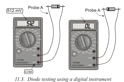
Digital instruments have a position on the dial to measure diodes, as shown in 11.1b. When we connect probes to each other, the multimeter should buzz, which signals a short circuit, and display tells 0. When we separate the probes the buzzing stops, and a symbol for open circuit is displayed (this can be either 0L or 1). Now we connect probes to the diode (11.3a). Then we reverse the diode and connect it again (11.3b). If the measured diode was ok, one of the two measurements would have shown a value which represents a minimum voltage that could be conducted through the diode (between 400mV and 800mV), and the anode is the end of the diode which is connected to probe A (red one). The diode is faulty if you hear a buzz (closed circuit) or some value which represents infinity. Transistors are tested in a similar fashion, since they act as two connected diodes. According to 11.4b, the positive probe is connected to the base, and the negative probe is first connected to the collector and then the emitter. In both cases the resistance should be low. After that, you do the same thing, only with switched probes. The negative probe is connected to the base and you test the collector and emitter with a positive probe.
 Both cases should produce a high value on the meter.
When testing PNP transistors, all steps are the same, but the measurements should be opposite: on 11.4a they are high, and on 11.4c they are low.
Both cases should produce a high value on the meter.
When testing PNP transistors, all steps are the same, but the measurements should be opposite: on 11.4a they are high, and on 11.4c they are low.
 If you test transistors using a digital instrument, the process remains similar to the one with diodes. Each diode should produce a value between 400mV and 800mV. Many modern digital multimeters have a socket for testing transistors. There is, as displayed on 11.5, a special socket where low and medium power transistors fit. If you need to test high power transistors, thin wires (0.8mm) should be soldered to transistor's pins and then plugged into the socket. As displayed on 11.5, a transistor is plugged into the socket according to its type (PNP or NPN) and the switch with a hFE marking is brought into position. If the transistor works, the display shows a value which represents the current amplification coefficient. If, for example, a transistor is tested, and the display shows 74, this means the collector current is 74 times higher than the base current.


