4.6 Interrupts
The AT89S8253 has in total of six interrupt sources, which means that it can recognize up to 6 different events that can interrupt regular program execution. Each of these interrupts can be individually enabled or disabled by setting bits of the IE register, whereas the whole interrupt system can be disabled by clearing the EA bit of the same register.
Since this microcontroller has embedded Timer T2 and SPI (they don't fall under the “8051 Standard”) which can generate an interrupt, it was necessary to make some changes in registers controlling interrupt system. Besides, there is a new interrupt vector (address 2B), i.e. program memory address from which the program proceeds with execution when the Timer T2 generates an interrupt. All these changes are made on the previously unused bits. This enables all programs written for the previous versions of the microcontrollers to be used in this one too without being modified. This is why the 8051-based microcontrollers are so popular.
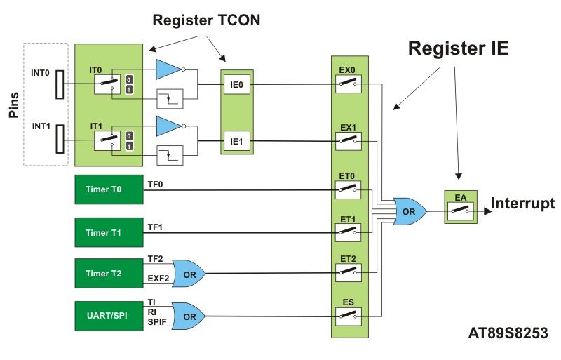
IE register (Interrupt Enable Register)

EA bit enables or disables all interrupt sources (globally):
- 0 - disables all interrupts (even enabled).
- 1 - enables specific interrupts.
ET2 bit enables or disables Timer T2 interrupt:
- 0 - Timer T2 interrupt disabled.
- 1 - Timera T2 interrupt enabled.
ES bit enables or disables serial communication (UART and SPI) interrupts:
- 0 - UART and SPI interrupt disabled.
- 1 - UART and SPI interrupts enabled.
ET1 bit enables or disables Timer T1 interrupt:
- 0 - Timer T1 interrupt disabled.
- 1 - Timer T1 interrupt enabled.
EX1 bit enables or disables external interrupt through the INT0 pin:
- 0 - Interrupt on the INT0 pin disabled.
- 1 - Interrupt on the INT0 pin enabled.
ET0 bit enables or disables Timer T0 interrupt:
- 0 - Timer T0 interrupt disabled.
- 1 - Timer T0 interrupt enabled.
EX0 bit enables or disables external interrupt through the INT1 pin:
- 0 - Interrupt on the INT1 pin disabled.
- 1 - Interrupt on the INT1 pin enabled.
Interrupt Priorities
When several interrupts are enabled, it may happen that while one of them is in progress, another one is requested. In such situations, the microcontroller needs to know whether to proceed with the execution of current interrupt routine or to meet a new interrupt request. For this reason, there is a priority list on the basis of which the microcontroller knows what to do. The previous versions of the microcontrollers differentiate between two priority levels defined in the IP register.
As for the AT89S8253 microcontroller, there is an additional SFR register IPH which enables all the interrupts to be assigned 1 out of 4 priorities (excluding reset). Here is a list of priorities:
- Reset. If a reset request arrives, all processes are stopped and the microcontroller restarts.
- The high priority interrupt (3) can be disabled by reset only.
- The low priority interrupt (2, 1 or 0) can be disabled by any high priority interrupt and reset.
It is usually defined at the beginning of the program which one of the existing interrupt sources have high and which one has low priority level. According to this, the following occurs:
- If two interrupt requests, at different priority levels, arrive at the same time then the higher priority interrupt is always serviced first.
- If the both interrupt requests, at the same priority level, occur one after another, the one which came later has to wait until routine being in progress ends.
- If two interrupt requests of equal priority arrive at the same time then the interrupt to be serviced is selected according to the following priority list :
- External interrupt INT0
- Timer T0 interrupt
- External interrupt INT1
- Timer T1 interrupt
- Serial communication interrupt
- Timer T2 Interrupt
IP register (Interrupt Priority Register)

Bits of this register determine the interrupt source priority.
PT2 Timer T2 interrupt priority:
- 0 - Priority 0
- 1 - Priority 1
PS Serial port interrupt priority:
- 0 - Priority 0
- 1 - Priority 1
PT1 Timer T1 interrupt priority:
- 0 - Priority 0
- 1 - Priority 1
PX1 External interrupt INT1 priority:
- 0 - Priority 0
- 1 - Priority 1
PT0 Timer T0 interrupt priority:
- 0 - Priority 0
- 1 - Priority 1
PX0 External interrupt INT0 priority:
- 0 - Priority 0
- 1 - Priority 1
IPH Register (Interrupt Priority High)
 PT2H
PT2H Timer T2 interrupt priority
PSH Serial port interrupt priority
PT1H Timer T1interrupt priority
PX1H External interrupt INT1 priority
PT0H Timer T0 interrupt priority
PX0H External interrupt INT0 Priority
Bits of this register can be combined with appropriate bits of the IP register. This is how a new priority list with 4 interrupt priority levels (5 including reset) is obtained.
| IP BIT |
IPH BIT |
INTERRUPTS |
| 0 |
0 |
Priority 0 (lowest) |
| 0 |
1 |
Priority 1 (low) |
| 1 |
0 |
Priority 2 (high) |
| 1 |
1 |
Priority 3 (highest) |
Processing interrupt
When an interrupt request arrives, the microcontroller automatically detects the interrupt source and the following occurs:
- Instruction in progress is ended;
- The address of the next instruction to execute is pushed onto the stack;
- Depending on which interrupt is requested, one of five vectors (addresses) is written to the program counter according to the table below:
| INTERRUPT SOURCE |
JUMP ADDRESS |
| IE0 |
3h |
| TF0 |
Bh |
| IE1 |
13h |
| TF1 |
1Bh |
| RI, TI, SPIF |
23h |
| TF2, EXF2 |
2Bh |
| All addresses are in hex format |
Appropriate subroutines processing interrupts are stored at these addresses. Instead of them, there are usually jump instructions specifying locations at which these subroutines reside.
4. When an interrupt routine is executed, the address of the next instruction to be executed is popped from the stack to the program counter and the program proceeds from where it left off.


