7.2 Easy8051A Development System
The Easy8051A development system is a high-quality development system used for programming 8051 compatible microcontrollers manufactured by Atmel. In addition to chip programming, this system enables all the parts of the program to be tested as it contains most components which are normally built in real devices.
The Easy8051A development system consists of:
- Sockets for placing microcontrollers in (14, 16, 20 and 40- pin packages)
- Connector for external power supply (DC 12V)
- USB programmer
- Power Supply Selector (external or via USB cable)
- 8 Mhz Quartz Crystal Oscillator
- 32 LEDs for output pin state indication
- 32 push buttons for input pin activation
- Four 7-segment LED displays in multiplex mode
- Graphic LCD display
- Alphanumeric LCD display (4- or 8- bit mode)
- Connector and driver for serial communication RS232
- Digital thermometer DS1820
- 12- bit A/D converter (MCP3204)
- 12- bit D/A converter (MCP4921)
- Reference voltage source 4.096V (MCP1541)
- Multiple-pin connectors for direct access to I/O ports
The following text describes in short some circuits within this development system. It is rather illustration of its features than complete manual. Besides, by learning about this device, one understands that microcontrollers and its tools are intended to everybody, not only to the privileged.
Sockets
All microcontrollers manufactured by Atmel appear in a few standard DIP packages. In order to enable their programming using one device, corresponding pins (having the same name) on sockets are connected in parallel. As a result, by being placed in the appropriate socket, each microcontroller is automatically properly connected. Figure on the right shows a microcontroller in 40-pin package and connection of one of its I/O pins (P1.5). As seen, the pin can be connected to an external device (connector PORT1), LED (microswitch SW2), push button or resistor through connectors. In the last two cases, polarity of voltage is selected using on-board jumpers.


Programmer
The purpose of the programmer is to transfer HEX code from PC to appropriate pins and provide regular voltage levels during chip programming as well. For this development system, the programmer is built in it and should be connected to PC via USB cable. When the process of programming is completed, pins used for it are automatically available for other application.


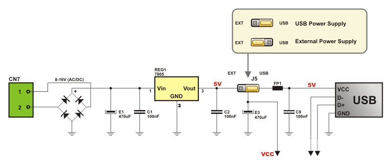
Development system power supply
There is a connector on the development board enabling commection to external power supply source (AC/DC, 8-16V). Besides, voltage necessary for device operation can also be obtained from PC via USB cable. Jumper J5 is used for power supply selection.

8MHz Oscillator
The EASY8051A development system has built-in oscillator used as a clock signal generator. The frequency of this oscillator is stabilized by 8Hz quartz crystal. Besides, it is also possible to select internal RC oscillator during chip programming,.


LEDs for output pin state indication
Each I/O port pin is connected to one LED which enables visual indication of its logic state. In the event that the presence of directly polarized LEDs and serial resistors is not acceptable in some applications, DIP switch SW2 enables them to be disconnected from the port.


Push buttons for input pin activation
Similar to LEDs, each I/O port pin is connected to one push button on the development board. It enables simple activation of input pins. Jumper J6 is used for selecting voltage polarity (+ or -) brought to pins by pressing appropriate push button.


7-segment LED displays
Being often applied in the industry, four high-performance LED displays set in multiplex mode belong to the development system. Display segments are connected to the port P0 via resistors. Transistor drivers used for activating individual digits are connected to the first four port P1 pins. It enables programs using 7-segment displays to be tested with minimum use of I/O ports. Similar to LEDs, DIP switch SW2 enables transistor drivers to be disconnected from microcontroller pins.


LCD displays
The EASY8051A development system provides connection to eather graphic or alphanumeric LCD display. Both types of displays are connected by being placed into appropriate connector and by switching position of the jumper J8. If displays are not in use, all pins used for their operation are available for other applications. Apart from connectors, there is also a potentiometer for contrast regulation on the board.


Serial communication via RS232
Similar to other built-in circuits, electronics supporting serial communication can be enabled or disabled by using jumpers J9 and J10.
In order to enable programs using serial communication to be tested, the development system has built in standard 9-pin SUB-D connector. The MAX232 is used as a voltage regulator.


DS1820 Digital thermometer
Temperature measurement is one of the most common tasks of devices which operate in the industry. For this reason, there is a circuit DS1820 on the EASY8051A development system which measures temperature in the range of -55 to +125oC with accuracy greater than 0.50. Results of measurement are transferred via serial communication to the pins P3.3 or P2.7. Jumper J7 is used for selecting pins for data reception. In the event that no jumper is installed, port pins are available for other applications.


12-bit A/D converter MCP3204
A built-in 12-bit AD Converter MCP3204 has four input channels connected to on-board connectors. Data are interchanged with the microcontroller via SPI serial communication system using pins P1.5, P1.6, P1.7 and P3.5. If A/D converter is not in use, these pins can be used for other applications (DIP switch SW1). In order to check operation, there is a potentiometer on the development board used as a variable voltage source. It can be brought to the converter’s input pins using one of four jumpers J12. As a special convenience, a reference voltage source MCP1541 (4,096V) is built in. Jumper J11 is used to select whether converter will use this voltage or 5V.


12-bit D/A converter MCP4921
Digital to analog conversion (D/A) is another operation ofen performed by the microcontroller in practice. For this reason, there is a special on-board chip which interchanges data with the microcontroller via SPI communication system. It can also generate analog voltage in 12-bit resolution on its output pin. When it is not in use, all microcontroller pins are available for other applications using DIP switch SW1. Similar to A/D converter, jumper J11 is used for selecting reference voltage.


Connectors for direct access to I/O ports
In order to enable microcontroller ports to be directly connected to additional components, each of them is connected to one on-board connector. Besides, two pins of each connector are connected to power supply voltage while each pin can be connected to + or - polarity of voltage via resistors (pull up or pull down resistors). Presence and connection of these resistors are determined by jumpers. Jumper J3 which controls port P3 is shown in figure on the right.


