


OFF
GO LOCAL
| Company | Stock | Price |
|---|---|---|

MIKROE-1535
35 g
Status:
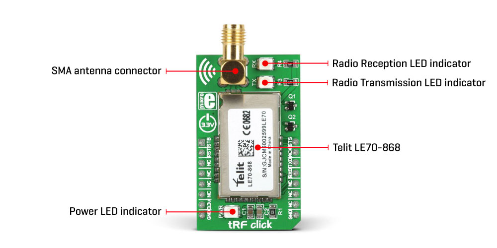
tRF Click is a compact add-on board with a complete short-range RF communication solution operating in the 868MHz ISM license-free frequency band. This board features the LE70-868, a short-range wireless module from Telit Cinterion. It features the complete RF, software stack, and packet handling onboard, exposing just a simple UART interface and offering a familiar Hayes AT command set. Using the Telit proprietary protocol, it can be used in PTP (Point to Point) or Star topology wireless networks. The module can also operate as a smart repeater, greatly improving the network range. This Click board™ makes the perfect solution for applications such as energy monitoring, for windmills and solar panels, weather stations and irrigation.
tRF Click is supported by a mikroSDK compliant library, which includes functions that simplify software development. This Click board™ comes as a fully tested product, ready to be used on a system equipped with the mikroBUS™ socket.
This product is no longer in stock
Availability date:
OFF
| Company | Stock | Price |
|---|---|---|
tRF Click is based on the LE70-868, a short-range wireless module from Telit Cinterion. Due to its robustness and simplicity, it is ideally suited for replacing communication over cables, such as RS485 links (Profibus, Modbus) and half-duplex RS232 links, with wireless technology. With the features such as Listen Before Talk (LBT), AES 128 encryption, excellent RX sensitivity of -117 dBm, 15 to 27 dBm output power, error reporting, and more, it is a perfect choice for establishing secure and reliable long-range network coverage, even in noisy environments.
This module is composed of digital and RF sections. The RF section is responsible for frequency synthesis, packet handling, power amplification, and low noise reception. This module has a maximum power of 500mW, staying compliant with the ERC recommendation 70-03, Annex 1. The digital section takes care of all the I/O management and communication interface. The embedded MCU with the Telit software stack is also a part of this section. The module can be switched to command mode when it receives the command string (+++) via the UART. While configured to work in a command mode, it is possible to set the values of the registers. The radio communication is stopped while in this mode. The LE70-868 RF module documentation shows a list of registers, allowing a simplified device configuration.
This module can operate in three different modes. In Transparent mode, its default mode, data is sent without addressing or encapsulation. Data sent to the UART RX pin of the module is sent over the air transparently as it is, where up to 115.2 kbps communication speed via UART is supported. All modules in range operating on the same radio frequency can receive the data. The Addressed Secured mode uses frame addressing, CRC check, and acknowledgment. It allows a multipoint network to be realized, in which every module can communicate with other network modules. This mode also allows telemetry commands to be sent over the network and supports broadcasting (when sending data at address 0). Data is buffered before sending, so the frames should remain small enough to fit in the buffer.
The Smart Repeater mode allows data communication between the coordinator and the end nodes, extending the function of the Addressed Secured mode. It allows every type of network distribution to be established - star topology, line topology, and a combination of these two. It can be used to extend the range of the network. Some additional features include LBT (Listen Before Talk), a feature that performs radio frequency scanning before it sends data, ensuring the radio band is free - avoiding data collisions. It works for both Transparent and Addressed modes. AES 128-bit data encryption helps achieve the required network security, while the Wake on Radio feature allows low power consumption, allowing modules to remain in Sleep mode, waking up periodically. The module wakes up entirely and processes the message when valid frames are received.
As mentioned, tRF click uses the UART interface to communicate with the host MCU supporting speed from 1.2 kbps to 115.2 kbps. In addition, the module is equipped with several configurable I/O pins. By default, they are used by the module to report status or as the control inputs. The IO9 pin is routed to the mikroBUS™ PWM pin labeled as STS. This pin goes HIGH, during transmission over the serial port. While idle, it stays at the LOW logic level. The IO8 pin is routed to the mikroBUS™ INT pin labeled as ACK. In Addressed Secured mode, this signal goes to logic HIGH when an ACK notification is not received after frame transmission and repetition. The WKP/STB pin is used to wake the module or put it into standby mode. When the standby mode register S240 has the bit 0 set, while this pin stays at a HIGH logic level, the module will be in standby mode. The module will wake on the falling edge of this pin. It is routed to the mikroBUS™ AN pin labeled as STB. The #RESET pin is internally pulled up with a resistor. A LOW logic level on this pin will reset the embedded MCU of the module. It is routed to the RST pin of the mikroBUS™.
The IO1 and IO2 pins are used to report network status by LEDs. The IO1 pin is routed to a red LED labeled TX, used to report any radio transmission from the module. The IO2 pin is routed to the yellow LED labeled RX, which reports any radio reception before the application layer processes it, activated when registers S261 and S262 are set to 0, respectively. SMA antenna connector is also included, allowing an 868MHz antenna to be connected for the optimal range of the module.
This Click board™ can only be operated with a 3.3V logic voltage level. The board must perform appropriate logic voltage level conversion before using MCUs with different logic levels. However, the Click board™ comes equipped with a library containing functions and an example code that can be used, as a reference, for further development.
Type
Sub-1 GHz Transceievers
Applications
Can be used for replacing communication over cables, such as RS485 links and half-duplex RS232 links, with wireless technology, either transparently, in a secured star or line network topology
On-board modules
LE70-868 - short-range wireless module from Telit Cinterion
Key Features
A complete proprietary Telit software stack onboard, a wide area coverage of up to 10km, AES 128bit encryption, and excellent RX sensitivity, operates in the 868MHz ISM license-free frequency band, onboard SMA antenna connector for optimal range, configurable output power, and more
Interface
UART
Feature
No ClickID
Compatibility
mikroBUS™
Click board size
M (42.9 x 25.4 mm)
Input Voltage
3.3V
Category
Click Boards
This table shows how the pinout on tRF click corresponds to the pinout on the mikroBUS™ socket (the latter shown in the two middle columns).
| Notes | Pin | Pin | Notes | ||||
|---|---|---|---|---|---|---|---|
| Standby/Wakeup | STB | 1 | AN | PWM | 16 | STS | UART TX Status |
| Reset | RST | 2 | RST | INT | 15 | ACK | Acknowledgement |
| NC | 3 | CS | RX | 14 | TXD | UART Transmit | |
| NC | 4 | SCK | TX | 13 | RXD | UART Receive | |
| NC | 5 | MISO | SCL | 12 | NC | ||
| NC | 6 | MOSI | SDA | 11 | NC | ||
| Power supply | 3.3V | 7 | 3.3V | 5V | 10 | NC | |
| Ground | GND | 8 | GND | GND | 9 | GND | Ground |
| Label | Name | Default | Description |
|---|---|---|---|
| LD1 | PWR | - | Power LED indicator |
| LD2 | TX | - | Transmission LED Indicator |
| LD3 | RX | - | Reception LED Indicator |
| Description | Min | Typ | Max | Unit |
|---|---|---|---|---|
| Supply Voltage | - | 3.3 | - | V |
| Frequency Range | 863 | - | 870 | MHz |
| Radio Data Rate | 4.8 | - | 57.6 | Kbps |
| Output Power | 15 | - | 27 | dBm |
| Sensitivity | - | -117 | - | dBm |
| Range | - | - | 10 | km |
We provide a library for the tRF click on our LibStock page, as well as a demo application (example), developed using MikroElektronika compilers. The demo can run on all the main MikroElektronika development boards.
Library Description
Initializes and defines UART bus driver, and defines driver's functions for comunication (reading and writing) between tRF clicks.
Key functions:
void trf_writeByte(uint8_t input) - Function writes (sends) one byte in UART rx bufferuint8_t trf_readByte() - Function reads (receives) one byte from UART rx bufferuint8_t trf_byteReady() - Function checks state of rx buffer (is new data placed in)void trf_reset() - Function resets click and sets back in normal operating modeExample description
The application is composed of three sections:
void applicationTask()
{
 char tmp;
 uint8_t rdyFlag;

// RECEIVER - UART polling

 rdyFlag = trf_byteReady();

 if (1 == rdyFlag)
 {
 tmp = trf_readByte();
 mikrobus_logWrite( &tmp, _LOG_BYTE );
 }

// TRANSMITER - TX each 2 sec

 /*for (tmp = 0; tmp < 9; tmp++)
 {
 trf_writeByte( MESSAGE_DATA[tmp] );
 mikrobus_logWrite( "MESSAGE SENT", _LOG_LINE );
 Delay_100ms();
 }
 Delay_ms(2000);*/
}
${EXAMPLE_ADDITIONAL_FUNCTIONS}
The full application code, and ready to use projects can be found on our LibStock page.
Other mikroE Libraries used in the example:
Additional notes and information
Depending on the development board you are using, you may need USB UART click, USB UART 2 click or RS232 click to connect to your PC, for development systems with no UART to USB interface available on the board. The terminal available in all MikroElektronika compilers, or any other terminal application of your choice, can be used to read the message.
This click board is supported with mikroSDK - MikroElektronika Software Development Kit. To ensure proper operation of mikroSDK compliant click board demo applications, mikroSDK should be downloaded from the LibStock and installed for the compiler you are using.
For more information about mikroSDK, visit the official page.

$8.28

$889.00

$8.28

$95.00

$549.00

$299.00

$29.00

$29.00

$6.59

$3.60

$119.00

$299.00

$449.00

$349.00

$349.00

$349.00

$269.00

$249.00

$209.00