


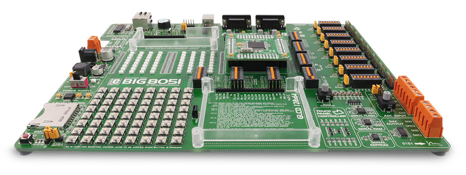
This board is a full-featured development environment for Silicon Labs C8051Fxxx microcontrollers. It has numerous on-board modules that help you to create your prototype device easily. It comes with C8051f040 microcontroller.

MIKROE-598
1200 g
Status:
The BIG8051 development system supports 100-pin Silabs 8051 microcontrollers. It comes with the c8051f040 microcontroller. The system is delivered with a Silabs USB 2.0 programmer and many peripheral modules such as Serial Ethernet, DAC, ADC etc.
This product is no longer in stock
Availability date:
20%
OFF
This board is a full-featured development environment for Silicon Labs C8051Fxxx microcontrollers. It has numerous on-board modules that help you to create your prototype device easily. It comes with C8051f040 microcontroller.
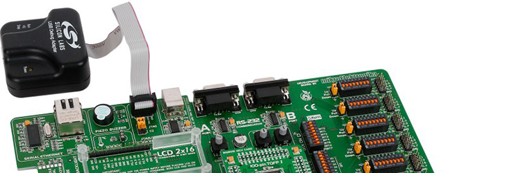
Programming. System comes with fast USB Debug Adapter - programmer from Silicon Laboratories.The USB Debug Adapter provides the interface between the PC’s USB port and the C8051Fxxx’s in-system debug/programming circuitry.
Storage. MMC/SD Card slot allows you to store large ammounts of data externally on MMC/SD card using fast SPI communication. Store up to 8 Mbit of data in M25P80 Serial Flash Memory with 25 MHz SPI Bus Interface. It suports over 100,000 Erase/Program Cycles per Sector and has over 20 Year Data Retention. You can store 8x256 bytes of configuration data or other data into on-board 24AA01 Serial EEPROM with I2C interface. On-board Serial RAM memory based on 23K640 offers you the power to store your variables and temporary calculation results, and therefore free on-chip RAM for other purposes.
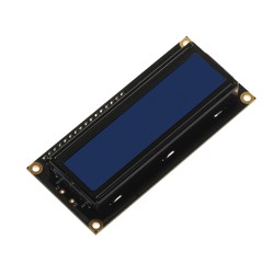
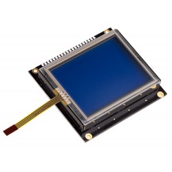
Displays and Touch screen. Graphic LCD 128x64 and LCD 2x16 can be easily connected via the on-board connectors. Board also features a Touch Screen controller.
PORTs, buttons and LEDs. 64 Buttons have stable operation and exceptional response curve. Ergonomy is at highest level so you will feel a great difference compared to other widely used standard switches. Monitor your program execution, or create all sorts of visual signalization using on-board 64 LEDs. SMD LEDs emmit high power red light.
Communication and Interfaces. RS-232 communication is enabled via two DB9 connectors and MAX232 level converters. USB connector, CAN transceiver MCP2551 and a serial Ethernet module are provided on-board as well.
Powering the board using USB-UART connector. USB-UART connector can be used to provide the power to the board. You should be able to run all on-board modules, including GLCD display and Ethernet. You should know that you can draw maximum of 500mA from the PC USB port.
DAC, ADC, Comparators. Convert digital signals to analog voltage levels using 12-bit MCP4921 DAC chip with SPI interface. It has two separate DAC channels and is connected to output Screw Terminal. You can attach four analog inputs using hi-quality ADC Input Screw Terminal Connectors. They are connected to CH0 – CH3 analog channels of the microcontroller. You can use on-chip comparator module with all it’s features and advantages, and test your program using comparator potentiometers connected to CP0+ and CP0- pins.
| Type | 7th Generation |
| Architecture | 8051 (8-bit) |
| Programming | USB |
| Silicon Vendor | Silicon Labs |
| MCU Socket | MCU card 7th gen |
| Supply Voltage | External |
| Category | 7th Generation |
NOTE: Please be advised that any peripheral devices or accessories shown connected to the Click board™ are not included in the package. Check their availability in our shop or in the YMAN section below.
$7.84
$31.20
$5.92
$3.60

$389.60