


20%
OFF

MIKROE-2035
20 g
Status:
Stepper 3 Click is a compact add-on board that contains a bipolar stepper motor driver. This board features the ULN2003A, a high-voltage, high-current Darlington transistor array from Texas Instruments. It is designed to drive unipolar stepper motors with a supply voltage applied to the common wire. The current flows through the common wire and the motor coil via the activated current sink driver to the ground. This allows driving unipolar stepper motors up to 30V and 500mA per coil. The ULN2003A itself is an ideal option for driving inductive loads such as the motor coils, as every channel is equipped with the common cathode clamp diode, which protects the IC from back EMF, typically observed at inductors and coils. This Click board™ makes the perfect solution for the development of small stepping motors in various applications such as consumer electronics and industrial equipment.
Stepper 3 click is supported by a mikroSDK compliant library, which includes functions that simplify software development. This Click board™ comes as a fully tested product, ready to be used on a system equipped with the mikroBUS™ socket.
This product is no longer in stock
Availability date:
Stepper 3 Click is based on the ULN2003A, a high-voltage, high-current Darlington transistor array from Texas Instruments. Motor step progression is performed by alternating the active driver, which sinks the current through the coil connected to the respective driver. The MCU performs the alteration cycle, which controls the driver inputs: a HIGH logic level on the input pin will set the corresponding driver to a LOW logic level, allowing it to sink current. Besides driving a unipolar stepper motor as the primary function, this Click board™ can also be used for driving relays and brushed DC motors or as the logic buffer for various applications. Combining more than one driver makes it possible to sink more than 500mA.
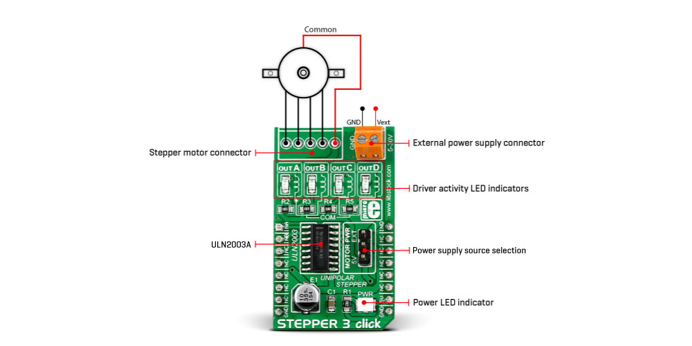
Stepper 3 Click uses four GPIOs to allow the host MCU to control the stepper motor or other mentioned device. Those pins are labeled as INA, INB, INC, and IND. Four output channels from the ULN2203A and a motor power supply are routed to the unpopulated 5-pin header. The motor can be powered over the 5V rail of the mikroBUSTM socket or the external power supply terminal with voltages of 5 – 30V. The selection can be made over the MOTOR PWR jumper. In addition, the ULN2003As output channels are also routed to the four output LEDs (outA, outB, outC, and outD) for a visual presentation.
This Click board™ can be operated only with a 5V logic voltage level. The board must perform appropriate logic voltage level conversion before using MCUs with different logic levels. Also, it comes equipped with a library containing functions and an example code that can be used as a reference for further development.
Type
Stepper
Applications
Can be used for the development of unipolar stepper motor control applications. Besides, it can also be used for driving relays, brushed DC motors, etc
On-board modules
ULN2003A - high-voltage high-current Darlington transistor array from Texas Instruments
Key Features
High-power Darlington sink drivers with up to 500mA per channel, clamping diode for the kickback voltage protection, can be used for other applications such as driving relay coils or brushed DC motors, selectable power source, and more
Interface
GPIO
ClickID
No
Compatibility
mikroBUS™
Click board size
M (42.9 x 25.4 mm)
Input Voltage
5V
This table shows how the pinout on Stepper 3 click corresponds to the pinout on the mikroBUS™ socket (the latter shown in the two middle columns).
| Notes | Pin | Pin | Notes | ||||
|---|---|---|---|---|---|---|---|
| Channel A ctrl IN | INA | 1 | AN | PWM | 16 | IND |
Channel D ctrl IN |
| Channel B ctrl IN | INB | 2 | RST | INT | 15 | NC | |
| Channel C ctrl IN | INC | 3 | CS | RX | 14 | NC | |
| NC | 4 | SCK | TX | 13 | NC | ||
| NC | 5 | MISO | SCL | 12 | NC | ||
| NC | 6 | MOSI | SDA | 11 | NC | ||
| NC | 7 | 3.3V | 5V | 10 | 5V | Power supply | |
| Ground | GND | 8 | GND | GND | 9 | GND | Ground |
| Label | Name | Default | Description |
|---|---|---|---|
| LD1 | PWR | - | Power LED indicator |
| LD2 | outA | - | Channel A LED Indicator |
| LD3 | outB | - | Channel B LED Indicator |
| LD4 | outC | - | Channel C LED Indicator |
| LD5 | outD | - | Channel D LED Indicator |
| J1B | MOTOR PWR | - | Motor Power Supply Source Selection 5V/EXT: Down position 35V, Up position EXT |
| Description | Min | Typ | Max | Unit |
|---|---|---|---|---|
| Supply Voltage | - | 5 | - | V |
| External Power Supply Voltage | 5 | - | 30 | V |
| Current Limit per Channel | - | - | 500 | mA |
We provide a library for the Stepper 3 Click as well as a demo application (example), developed using MIKROE compilers. The demo can run on all the main MIKROE development boards.
Package can be downloaded/installed directly from NECTO Studio Package Manager(recommended), downloaded from our LibStock™ or found on Mikroe github account.
Library Description
This library contains API for Stepper 3 Click driver.
Key functions
stepper3_set_step_mode This function sets the step mode resolution settings in ctx->step_mode.
stepper3_set_direction This function sets the motor direction to clockwise or counter-clockwise in ctx->direction.
stepper3_drive_motor This function drives the motor for the specific number of steps at the selected speed.
Example Description
This example demonstrates the use of the Stepper 3 click board by driving the motor in both directions for a desired number of steps.
void application_task ( void )
 {
     log_printf ( &logger, " Move 64 full steps clockwise rnn" );
     stepper3_set_step_mode ( &stepper3, STEPPER3_MODE_FULL_STEP );
     stepper3_set_direction ( &stepper3, STEPPER3_DIR_CW );
     stepper3_drive_motor ( &stepper3, 64, STEPPER3_SPEED_FAST );
     Delay_ms ( 1000 );
     Delay_ms ( 1000 );

     log_printf ( &logger, " Move 128 half steps counter-clockwise rnn" );
     stepper3_set_step_mode ( &stepper3, STEPPER3_MODE_HALF_STEP );
     stepper3_set_direction ( &stepper3, STEPPER3_DIR_CCW );
     stepper3_drive_motor ( &stepper3, 128, STEPPER3_SPEED_VERY_FAST );
     Delay_ms ( 1000 );
     Delay_ms ( 1000 );
 }
The full application code, and ready to use projects can be installed directly from NECTO Studio Package Manager(recommended), downloaded from our LibStock™ or found on Mikroe github account.
Other Mikroe Libraries used in the example:
Additional notes and informations
Depending on the development board you are using, you may need USB UART click, USB UART 2 Click or RS232 Click to connect to your PC, for development systems with no UART to USB interface available on the board. UART terminal is available in all MIKROE compilers.
This Click board™ is supported with mikroSDK - MIKROE Software Development Kit. To ensure proper operation of mikroSDK compliant Click board™ demo applications, mikroSDK should be downloaded from the LibStock and installed for the compiler you are using.
For more information about mikroSDK, visit the official page.
NOTE: Please be advised that any peripheral devices or accessories shown connected to the Click board™ are not included in the package. Check their availability in our shop or in the YMAN section below.

$711.20

$63.20

$359.20

$239.20

$29.00

$23.20

$4.39

$2.40

$79.20

$359.20

$279.20

$279.20

$279.20

$239.20

$215.20

$199.20

$167.20
